4.5. Architecture Exploration
Architecture exploration deals with the process of implementing a specification on a computation architecture consisting of PEs and memories in order to generate a respective architecture model for the design. Architecture exploration therefore helps designers to allocate PEs/memories, map design entities to the allocated PEs/memories and to generate the Architecture Model. Specifically, Architecture exploration consists of the following tasks:
PE Allocation to allocate and select PEs/memories from the PE database in order to assemble the system architecture (see Section 4.5.1).
PE Mapping to map the design's computation entities to the selected PEs/memories (see Section 4.5.2).
Architecture Refinement to automatically generate an Architecture Model from the given Specification Model based on the decision made during PE allocation and mapping (see Section 4.5.3).
Project Creation or Project Opening.
Preferences Editing and Project Settings Editing.
File Opening.
Design Adding.
Top-level Selection.
PE Allocation.
Mapping.
Architecture Refinement.
Project Saving and/or AE Exiting.
4.5.1. PE Allocation
Users can select PEs/memories out of the PE database in order to allocate and assemble the system architecture. PE allocation information is stored in the design itself as an allocation table that is annotated at the top-level design behavior (see Section 4.4.8). As a consequence, different allocation tables at different top-level behaviors can exist in the same design, reflecting the fact that incremental design will require changes in the allocation as design progresses from one part of the system to another.
Operation: In order to do PE allocation, users first select Main::Synthesis->Allocate PEs.... As a result, the current allocation is read from the design and a PE Allocation dialog is popped up. In case of errors reading the allocation from the design (e.g. wrong allocation table format), a new, empty allocation table is used in the dialog.
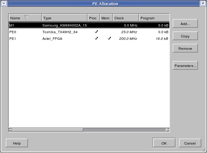
The PE Allocation dialog is shown in Section 4.5.1. In the PE Allocation dialog, the table shows the list of currently allocated PEs. The header of the table indicates the meaning of each column, such as PE's name and type. Each row in the table represents an allocated PE/memory that is part of the current system target architecture. For each PE, its name, its type, its capabilities (whether it is capable of arbitrary processing and whether it can implement shared variables exported to other PEs), its attributes and an editable description are shown in the respective columns of the table. The list of allocated PEs can be sorted by any column and in ascending or descending order each by clicking into the corresponding column header. By default, the list is sorted by ascending names.
In the PE Allocation dialog, users can perform the following actions:
- PE Adding
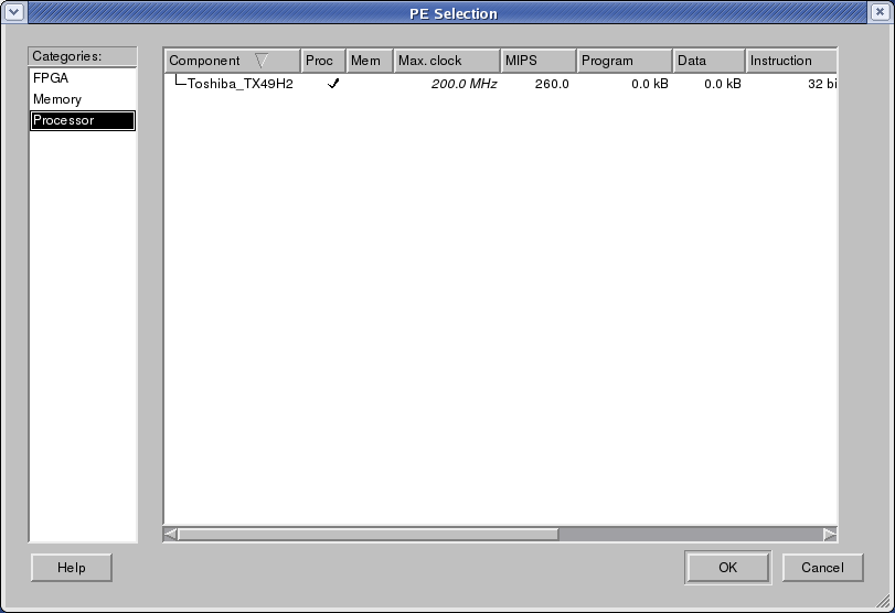
In order to add a PE into the design, users click the button Add... to pop up the PE Selection dialog which opens and loads the PE database and allows users to select an additional PE out of the PE database. The PE Selection dialog is shown in Figure 4-17.
At the left of the PE Selection dialog is a PE category table. Each row represents one category of PEs in the database. For example, row Processors contains all the general-purpose processors in the database.
By clicking and selecting one row in the table at left, users will be shown all the PEs in the selected category in the table at the right. Each row of the table at the right represents one type of PE in the database under the selected category. The name of the PE type is shown in the Component column. The Proc and Mem columns show the features of the PE, i.e. whether the PE is a general processor (is capable of executing arbitrary code/behavior) and whether the PE can act as a shared memory (is capable of exporting local storage to other PEs), respectively. Finally, other attributes of the PE type are displayed in separate columns. Users can select the desired PE type by clicking the corresponding row.
There are two buttons at the bottom of the PE Selection dialog: Ok and Cancel. By clicking the Ok button, an additional PE of the selected PE type and with an automatically determined name is added into the design's allocated architecture. In addition, PEs can be allocated by double-clicking into the desired PE type row in the PE Selection dialog (equivalent to selecting the row and pressing Ok). Clicking the Cancel button aborts and cancels PE selection without changes to the PE allocation. Either clicking Ok or Cancel button will close the PE Selection dialog and return to the PE Allocation dialog.
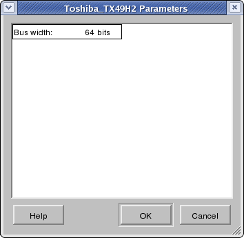
Components in the database can be parametrizable during instantiation. For such components, their type is shown in italic letters in the Component column. Furthermore, when allocating such a parametrizable component (by pressing the Ok button or by double-clicking on the component), a Component Parameter dialog will be popped up (see Figure 4-18). In this dialog, the user has to enter and confirm all parameters for the given component instance to be allocated. Users can enter any value for any parameter (within the value range allowed by the component) by clicking into each parameter's value field in the dialog. Clicking the Ok button of the dialog will generate a new customized component type with the selected parameters and will then allocate a new instance of this parametrized type. Clicking the Cancel button aborts component parametrization and returns to the PE Selection dialog.
- PE Copying
In order to duplicate an existing PE in the design's PE allocation, users can select a PE by clicking the corresponding row in the allocation table and click the button Copy. Clicking Copy will add a new PE instance with an automatically determined name and with the same type, attributes and description as the currently selected PE to the design's allocation.
- PE Deletion
In order to remove a PE from the design's allocation, users can select the target PE to be removed in the allocation table and click the Remove button. Clicking Remove will remove the selected PE from the list of allocated PEs.
- PE Editing
Users can edit the PE name and PE description in the PE Allocation dialog by clicking into the respective Name or Description column of the corresponding PE. Clicking into any of these cells will allow editing of the respective text in the cell by opening a text edit box in place. Pressing the Esc key during editing aborts the edit operation. Pressing Enter accepts the entered text and changes the PE name or description in the allocation accordingly.
- PE Parameter Viewing
Users can view the parameters assigned for parameterized components by clicking on the Parameters... button in the PE Allocation dialog after a component has been allocated. In this view, parameters are read-only and are uneditable. Clicking the Ok button closes the dialog.
- Allocation Closing
There are two buttons at the bottom of the PE Allocation dialog: Ok and Cancel. By clicking the Ok button, the allocation displayed in the PE Allocation dialog's allocation table is saved into the design. Clicking Cancel will abort and cancel PE Allocation. When cancelling, all modifications made to the allocation table will be lost and no data will be saved in the design. Either clicking Ok or Cancel button will close PE Allocation dialog.
Error/Information Messages: Before PE allocation, selecting Main::Synthesis->Allocate PEs... if no top-level behavior is selected in the design will pop up an Error dialog to that effect and will abort the PE allocation operation.
During PE editing, if users try to give PEs a name which is already used as the name of another PE in the design, an Error dialog will be popped up, a corresponding error message will be shown, and the editing operation will be aborted and cancelled.
During PE adding, when clicking the Add... button the PE database stored on disk will be opened and loaded in order to read the list of available PEs from the database. In case of errors during database opening (e.g. file errors or wrong file format), an Error dialog will be popped up and the PE adding operation will be aborted.
Furthermore, when adding a PE to the allocation via the PE Selection dialog, the selected PE type is read from the database. In case of database read errors (file errors, database format errors) during this operation, an Error dialog will be popped up and the PE adding operation aborted.
Finally, during PE allocation, clicking the Ok button in the PE Allocation dialog will write the allocation table back to the design. In case of errors, an Error dialog is popped up and PE allocation is aborted completely.
4.5.2. PE Mapping
In order to implement the computation in the specification model on the allocated computation architecture consisting of PEs and memories, users have to be able to map the behaviors, variables and channels in the specification onto the allocated PEs. Hence, mapping consists of separate behavior mapping, variable mapping and channel mapping tasks:
- Behavior Mapping
Behavior mapping allows for mapping of behavior types/classes in the design onto allocated PEs, i.e. behavior mapping information is stored as annotations at the behavior classes in the design. In order to be able to map a behavior onto a PE, the PE out of the database must allow execution of arbitrary code on it (Proc feature in PE Allocation and PE Selection dialogs, see Section 4.5.1).
Users can explicitly map every behavior type on a PE. Explicit mapping will map all instances of that behavior onto the selected PE. If instances should be mapped to different PEs, selected instances have to be isolated first (see Section 4.4.3).
If a behavior is not mapped to any PE, all of its instances will be implicitly (and recursively) mapped onto the same PE as the parent behavior class in which they are instantiated in. If different instances are implicitly mapped to different PEs, appropriate copies of the behavior in each PE will be automatically generated during refinement.

Note that user must map all the behaviors under the top-level behavior to PEs either implicitly (by mapping the top-level behavior itself) or explicitly.
- Variable Mapping
Variable mapping allows for mapping of variable instances in the design into local memories of allocated regular PEs or into allocated global, shared memory PEs. Variable mapping information is stored as annotations attached to variable definitions inside a behavior class. As a result, multiple incarnations of the same variable in different instances of the parent behavior will all share the same mapping information.
If a variable is not explicitly mapped by the user, during refinement a local copy of the variable will be created in each PE accessing the variable. Refinement will also automatically insert necessary code (additional behaviors inside PEs and channels between PEs) for synchronization and message passing to keep copies updated and synchronized such that shared semantics are preserved. Implicit mapping is not supported for variables that are shared among concurrent behaviors mapped to different PEs.
If a variable is explicitly mapped into local memory of a regular PE or into a shared, global memory PE, all of its incarnations will be moved there and other PEs will access the variable through a memory interface. Explicit mapping of variables is only supported for target PEs out of the database that support external accesses via a memory interface (Mem feature in PE Allocation and PE Selection dialogs, see Section 4.5.1).
- Channel Mapping
Channel mapping allows for mapping of complex channel instances (of c_queue or c_semaphore type) in the specification onto PEs in the allocated target architecture. Channel mapping information is stored as annotations attached to channel instantiations inside a behavior class. As a result, multiple incarnations of the same channel (instance) in different instances of the parent behavior will all share the same mapping information.
If a complex channel (instance) is explicitly mapped to a PE, implementations for all of its incarnations will be generated in that PE during refinement. If a complex channel (instance) is not explicitly mapped, implementations for each of its incarnations will be generated in the PE the parent behavior of that incarnation is mapped to. In both cases, other PEs accessing the channel incarnation will communicate with the target PE the channel incarnation is implemented in through additional automatically inserted simple channels.
In order to be able to map a channel onto a PE, the PE out of the database must allow execution of arbitrary code on it. (Proc feature in PE Allocation and PE Selection dialogs, see Section 4.5.1).
Operation: Users can map behaviors, variables and channels in a specification to allocated regular or memory PEs via the additional Mapping column in the Design Window hierarchy tab (Design::Hierarchy). Note that the Mapping column is only shown if PE allocation information is available (see Section 4.5.1). By default, the Mapping column shows the current mapping information for each entity in the design. In case of errors reading the mapping information from the design (e.g. wrong annotation format), an empty, implicit (i.e. lack of explicit) mapping will be assumed.
In order to explicitly map an entity, users should click into the Mapping column of the respective entity in the Design::Hierarchy tab. If the desired entities are not shown in the hierarchy tab, users should first enable display of variables or channels by selecting Main:View->Show Variables or Main:View->Show Channels. Note that clicks and interaction with the Mapping is disabled for items that are not mappable (e.g. items that are outside of the top-level design behavior).
Clicking into the Mapping column of the Design Window hierarchy tab of a specification model will open a drop-down combo box in place with entries for all possible target PEs in order allow users to select a target PE to map the entity to directly in the cell. In the combo box, users will be able to choose from all possible PEs that the specific entity can be mapped to (see above for enforced restrictions). In addition, the combo box contains an empty entry that can be chosen in order to remove any existing explicit mapping and switch to implicit mapping for that entity.
Selecting an entry from the combo box will write the corresponding mapping into the design. If there are multiple instances of an explicitly mapped entity (behavior class, variable definition or channel instance), the hierarchy tab display will be updated after changing the mapping to reflect the new mapping for all entity's instances in the Mapping column.
After mapping, the behaviors mapped to different PEs will be shown with different colors.
4.5.3. Architecture Refinement
Architecture refinement executes the implementation decisions made in the other architecture exploration tasks by refining the current Specification Model into an automatically generated Architecture Model based on and reflecting the decision made during PE allocation and mapping.
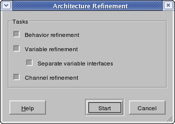
Operation: In order to do refinement, users select the Main::Synthesis->Architecture Refinement... menu entry. This will pop up the Architecture Refinement dialog. The Architecture Refinement dialog is shown in Figure 4-19.
In the Architecture Refinement dialog, users can select whether individual sub-tasks of the architecture refinement process will be performed or not. By checking or unchecking the check boxes tasks are turned on and off and partially or completely refined models can be generated. By default, all tasks are turned on. The three sub-tasks of architecture refinement are:
- Behavior Refinement
Behavior refinement introduces PE behaviors from the database, groups the original behaviors under the new PEs, and inserts synchronization and message passing to preserve execution semantics.
- Variable refinement
Variable refinement (re-)distributes variables into PEs, generates necessary PE memory interfaces, and updates accesses to shared variables inside leaf behaviors.
By checking or unchecking the Separate variable interfaces checkbox, users can select whether during variable refinement of memory-mapped I/O a separate memory interface is generated for each variable mapped to a synthesizable hardware PE (such that distinct base addresses can later be assigned to each variable/interface, see Section 4.7.1). If unchecked, a single, combined interface is generated for all variables mapped to a PE.
- Channel refinement
Channel refinement generates implementations of complex channels inside PEs, creates adapters for accesses to complex channel implementations, and inserts necessary simple channels in between.
User can then start the architecture refinement process by clicking the Start button. If users click the Cancel button, the architecture refinement operation will be aborted and cancelled. Either clicking Start or Cancel buttons will close the Architecture Refinement dialog.
After clicking the Start button, the architecture refinement command line components of SCE will be executed in the background. Any diagnostic, status and informative output of the architecture refinement tools will be shown in the refinement tab of the Output Window (Output::Refine).
When the architecture refinement process is finished, the newly generated architecture model is automatically opened and loaded, and a corresponding new Design Window is created in the Workspace. The new Design Window is automatically activated and raised to the front. In addition, the new Architecture Model is automatically added to the current project (see Section 4.2.5) as a child of the Specification Model it was generated from.
While the architecture refinement background tools are running, the majority of the main AE GUI is disabled. However, users can abort/kill execution of the background tools by selecting Main::Synthesis->Stop. After clicking, the current architecture refinement background task is aborted.
Error/Information Messages: While the architecture refinement tool is running, informational (e.g. progress and status reports) and error messages generated by the background tool are displayed in the Output::Refine tab of the Output Window.
If the architecture refinement background tools abort with an error (e.g. unmapped behaviors in the design) or are killed via the Main::Synthesis->Stop menu entry, a corresponding error message will be shown in Output::Refine and an Error dialog will pop up. Upon confirming the error, the remainder of the architecture refinement operation will be cancelled. Specifically, the architecture refinement background tools check for and can produce the following classes of errors:
No top level behavior.
No or invalid PE allocation.
No or invalid PE models in the database.
Unsupported (inter-PE) channels in the specification.
Unsupported (partitioned) behavior types in the specification.
Unsupported (global or partitioned) shared variable and/or port types in the specification.
No or invalid behavior or complex channel mapping.
Invalid variable mapping or no mapping for variables shared between concurrent behaviors on different PEs.
Finally, if the design the new model was generated from is not in the project, the new model is not added to the project and an Error dialog to that effect will be popped up.


