4.6. Network Exploration
Network Exploration is the main task of the Network Explorer tool. Network Exploration deals with the process of implementing end-to-end communication channels between PEs in the architecture model over point-to-point channels in a network of PEs, CEs and busses in order to generate the respective network model. Network Exploration therefore helps designers to allocate and define a communication topology and to generate a Network Model. Specifically, Network Exploration consists of five tasks:
Network Allocation to allocate, select and define the communication network topology (see Section 4.6.1).
Network Mapping to map the design's global, system-level channels to the selected network of busses (see Section 4.6.2).
Network Refinement to automatically generate a Network Model from the given Architecture Model based on the decisions made during Network Allocation (see Section 4.6.3).
In order to perform the network exploration, not all the tasks described above need to be done. However, some tasks must be executed and must be in a certain order. These mandatory tasks and their execution sequence are:
Project Creation or Project Opening.
Preferences Editing and Project Settings Editing.
File Opening.
Design Adding.
Network Allocation.
Network Mapping.
Network Refinement.
Project Saving and/or NE Exiting.
4.6.1. Network Allocation
In order to define the system network topology, users can allocate and connect (together with already allocated PEs) busses and CEs (bridges, transducers) out of the bus and CE databases, respectively. Network allocation and connection information is stored in the design itself as allocation and connection tables that are annotated at the top-level design behavior (see Section 4.4.8). As a consequence, different allocation/connection tables at different top-level behaviors can exist in the same design, reflecting the fact that incremental design will require changes in the topology as design progresses from one part of the system to another.
Operation: In order to do Network Allocation, users first select Main::Synthesis->Allocate Network. As a result, the current allocation and connectivity is read from the design and a Network Allocation dialog is popped up. In case of errors reading the allocation from the design (e.g. wrong allocation table format), new, empty allocation and connection tables are used in the dialog.
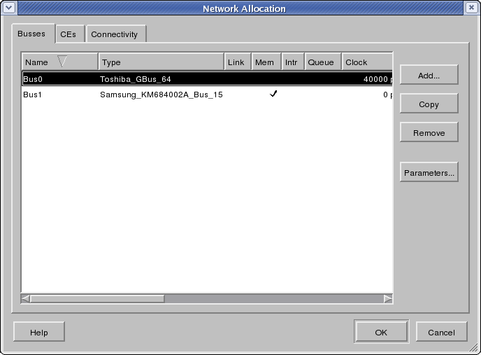
The Network Allocation dialog is shown in Figure 4-20. The Network Allocation dialog has three tabs, Bus, CE and Connectivity, in which the user can allocate busses, allocate CEs, or define the PE/CE to bus connectivity, respectively. Clicking the tabs at the top of the dialog will raise and shown the corresponding tab in front.
Note that as a result of previous architecture exploration, busses might be pre-allocated and pre-connected in the Architecture Model generated by the Architecture Explorer. The Architecture Explorer will automatically pre-allocate and pre-connect necessary and mandatory busses for PEs that come with pre-defined busses (i.e. CPUs). This information is then passed from the Architecture Explorer to the Network Explorer through the Architecture Model. As a result, such busses and their connectivity to PEs might show up when first opening the Network Allocation dialog for a new Architecture model.
In the Bus tab, a table with the list of currently allocated busses will be shown (Figure 4-20). The header of the table indicates the meaning of each column, such as bus name and type. Each row in the table represents an allocated bus that is part of the current system target architecture. For each bus, its name, its type, its capabilities (whether it supports link transfers, memory accesses, and/or interrupts and whether it acts as a queue), its attributes and an editable description are shown in the respective columns of the table. The list of allocated busses can be sorted by any column and in ascending or descending order each by clicking into the corresponding column header. By default, the list is sorted by ascending names. In the Bus tab of the Network Allocation dialog, users can perform the following actions:
- Bus Adding
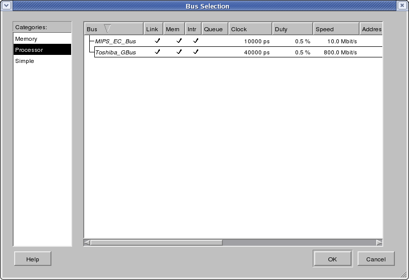
In order to add a bus to the design, users click the button Add to pop up the Bus Selection dialog which opens and loads the bus database and allows users to select an additional bus out of the bus database. The Bus Selection dialog is shown in Figure 4-21.
At the left of the Bus Selection dialog is a bus category table. Each row represents one category of busses in the database. For example, row Standard contains all the standard busses in the database.
By clicking and selecting one row in the table at left, users will be shown all the busses in the selected category in the table at the right. Each row of the table at the right represents one type of bus in the database under the selected category. The name of the bus type is displayed in the Bus column. The Link, Mem, Intr and Queue columns show the features of the bus, i.e. whether the bus supports link (packet/message) and/or memory (shared variable accesses or memory-mapped I/O) type transfers (optionally showing the number of supported transfer modes each), whether the bus provides interrupts for synchronization (marked with an `X' if synchronization is built into the bus) and whether the bus has queue semantics (with bus-internal buffers), respectively. Finally, other attributes of the bus type are displayed in separate columns. Users can select the desired bus type by clicking the corresponding row.
There are two buttons at the bottom of the Bus Selection dialog: Ok and Cancel. By clicking the Ok button, an additional bus of the selected bus type and with an automatically determined name is added into the design's allocated network architecture. In addition, busses can be allocated by double-clicking into the desired bus type row in the Bus Selection dialog (equivalent to selecting the row and pressing Ok). Clicking the Cancel button aborts and cancels Bus selection without changes to the bus allocation. Either clicking Ok or Cancel button will close the Bus Selection dialog and return to the Network Allocation dialog.
Components in the database can be parametrizable during instantiation. For such components, their type is shown in italic letters in the Component column. Furthermore, when allocating such a parametrizable component (by pressing the Ok button or by double-clicking on the component), a Component Parameter dialog will be popped up (see Figure 4-18 in Section 4.5.1). In this dialog, the user has to enter and confirm all parameters for the given component instance to be allocated. Users can enter any value for any parameter (within the value range allowed by the component) by clicking into each parameter's value field in the dialog. Clicking the Ok button of the dialog will generate a new customized component type with the selected parameters and will then allocate a new instance of this parametrized type. Clicking the Cancel button aborts component parametrization and returns to the Bus Selection dialog.
- Bus Copying
In order to duplicate an existing bus in the design's bus allocation, users can select a bus by clicking the corresponding row in the allocation table and click the button Copy. Clicking Copy will add a new bus instance with an automatically determined name and with the same type, attributes and description as the currently selected bus to the design's allocation.
- Bus Deletion
In order to remove a bus from the design's allocation, users can select the target bus to be removed in the allocation table and click the Remove button. Clicking Remove will remove the selected bus from the list of allocated busses. Busses that currently have PEs or CEs connected to them will not be available for deletion (the Remove button will be inactive and grayed out for them).
- Bus Editing
Users can edit the bus name and bus description in the bus allocation tab by clicking into the respective Name or Description column of the corresponding bus. Clicking into any of these cells will allow editing of the respective text in the cell by opening a text edit box in place. Pressing the Esc key during editing aborts the edit operation. Pressing Enter accepts the entered text and changes the bus name or description in the allocation accordingly.
- Bus Parameter Viewing
Users can view the parameters assigned for parameterized components by clicking on the Parameters... button in the Bus Allocation dialog after a component has been allocated. In this view, parameters are read-only and are uneditable. Clicking the Ok button closes the dialog.
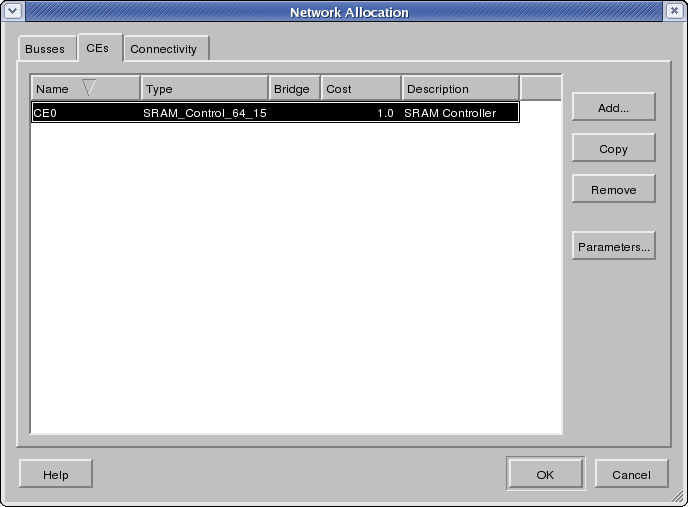
In the CE tab, a table with the list of currently allocated CEs will be shown (Figure 4-22). The header of the table indicates the meaning of each column, such as CE name and type. Each row in the table represents an allocated CE that is part of the current system target architecture. For each CE, its name, its type, its capabilities (whether it is capable of bus bridging at the lowest, protocol level), its attributes, and an editable description are shown in the respective columns of the table. The list of allocated CEs can be sorted by any column and in ascending or descending order each by clicking into the corresponding column header. By default, the list is sorted by ascending names. In the CE tab of the Network Allocation dialog, users can perform the following actions:
- CE Adding
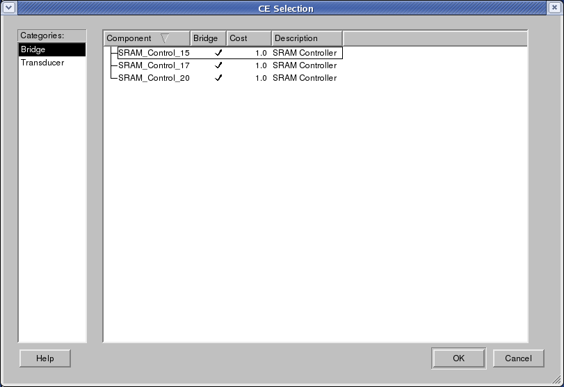
In order to add a CE to the design, users click the button Add to pop up the CE Selection dialog which opens and loads the CE database and allows users to select an additional CE out of the CE database. The CE Selection dialog is shown in Figure 4-23.
At the left of the CE Selection dialog is a CE category table. Each row represents one category of CEs in the database. For example, row Transducer contains all the transducers in the database.
By clicking and selecting one row in the table at left, users will be shown all the CEs in the selected category in the table at the right. Each row of the table at the right represents one type of CE in the database under the selected category. The name of the CE type is displayed in the Component column. The Bridge column shows the features of the CE, i.e. whether the CE is a bridge (is capable of bus bridging at the lowest, protocol level). Finally, other attributes of the CE type are displayed in separate columns. Users can select the desired CE type by clicking the corresponding row.
There are two buttons at the bottom of the CE Selection dialog: Ok and Cancel. By clicking the Ok button, an additional CE of the selected CE type and with an automatically determined name is added into the design's allocated network architecture. In addition, CEs can be allocated by double-clicking into the desired CE type row in the CE Selection dialog (equivalent to selecting the row and pressing Ok). Clicking the Cancel button aborts and cancels CE selection without changes to the CE allocation. Either clicking Ok or Cancel button will close the CE Selection dialog and return to the Network Allocation dialog.
Components in the database can be parametrizable during instantiation. For such components, their type is shown in italic letters in the Component column. Furthermore, when allocating such a parametrizable component (by pressing the Ok button or by double-clicking on the component), a Component Parameter dialog will be popped up (see Figure 4-18 in Section 4.5.1). In this dialog, the user has to enter and confirm all parameters for the given component instance to be allocated. Users can enter any value for any parameter (within the value range allowed by the component) by clicking into each parameter's value field in the dialog. Clicking the Ok button of the dialog will generate a new customized component type with the selected parameters and will then allocate a new instance of this parametrized type. Clicking the Cancel button aborts component parametrization and returns to the CE Selection dialog.
- CE Copying
In order to duplicate an existing CE in the design's CE allocation, users can select a CE by clicking the corresponding row in the allocation table and click the button Copy. Clicking Copy will add a new CE instance with an automatically determined name and with the same type, attributes and description as the currently selected CE to the design's allocation.
- CE Deletion
In order to remove a CE from the design's allocation, users can select the target CE to be removed in the allocation table and click the Remove button. Clicking Remove will remove the selected CE from the list of allocated busses.
- CE Editing
Users can edit the CE name and CE description in the CE allocation tab by clicking into the respective Name or Description column of the corresponding CE. Clicking into any of these cells will allow editing of the respective text in the cell by opening a text edit box in place. Pressing the Esc key during editing aborts the edit operation. Pressing Enter accepts the entered text and changes the CE name or description in the allocation accordingly.
- CE Parameter Viewing
Users can view the parameters assigned for parameterized components by clicking on the Parameters... button in the CE Allocation dialog after a component has been allocated. In this view, parameters are read-only and are uneditable. Clicking the Ok button closes the dialog.
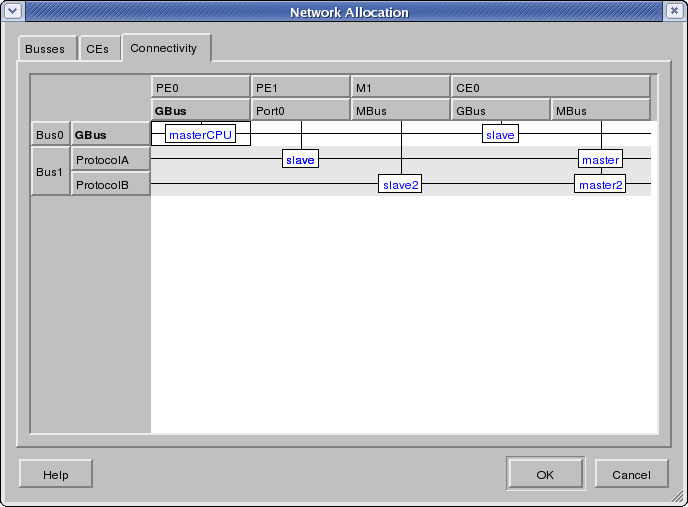
In the Connectivity tab, a matrix that displays connectivity of PEs and CEs to busses is shown (Figure 4-24). The top rows/headers of the connectivity table show all the currently allocated PEs and CEs together with the list of logical/interface ports for each PE/CE in the design. For each PE/CE and port, its name is shown in the respective header row. The list of PEs/CEs is automatically updated whenever a CE is added or deleted from the CE allocation in the CE tab. The rows of the connectivity matrix in the Connectivity tab list the currently allocated busses with their protocols in the design by their names. If a bus contains no protocols, the name is defaulted to the bus type. The list of busses is automatically updated whenever a bus is added or deleted from the bus allocation in the Bus tab. For each bus, the matrix visually shows the connectivity of ports to this bus by marking the corresponding columns. In the Connectivity tab of the Network Allocation dialog, users can perform the following actions:
- Port Adding/Deletion
The list of ports/interfaces for each PE and CE is determined by the list of available ports defined by the PE/CE database model. For synthesizable PEs/CEs with undefined or variable port lists in the database, the user can add or remove ports from the PE's or CE's port list. Right-clicking onto a PE's or CE's port list or port will pop up a context menu with the following entries:
- Add port...
Selecting Add port... will add an additional port with an automatically determined name to the corresponding PE or CE. This menu entry is not available (grayed out) for PEs or CEs with fixed port lists.
- Delete port
Selecting Delete port will remove the selected port from the corresponding PE or CE. This menu entry is not available (grayed out) for fixed/mandatory ports.
- Rename port
Selecting Rename port will open a text edit box in place in order to allow the user to edit the port name directly in the cell. Pressing Esc will abort editing while Enter accepts the new name. This menu entry is not available (grayed out) for fixed/mandatory ports.
- Port Connecting
In the table, the users can then connect ports of a PEs/CEs to busses by clicking into the corresponding table cell at the intersection of the port and bus. If the selected port is already connected to a different bus, the connection will be moved (i.e. the previous connection be removed and the port re-connected to the new bus). Ports with pre-defined, fixed protocols can only be connected to matching busses and clicking into any other bus row will have no effect. Pre-connected ports with mandatory, pre-defined and fixed bus connections can not be connected to any other bus, i.e. clicking into any row will have no effect.
For each port connection, the user can further specify the interface type of the port. Generally, ports can connected to busses either as bus master, bus slave or as combined bus master/slave. If the bus from the database supports arbitration and allows for multiple masters on the bus, any master connection must also specify the arbiter port to use where the bus database model defines the set of possible master ports supported by the bus. If the bus only supports interrupts but no regular masters or slaves, special connections ``wait'' and ``notify'' (optionally suffixed by the index of the selected interrupt bank/protocol) are available to connect a port on the bus' interrupt master (detection) and/or slave (generation) side, respectively.
Clicking into a valid (see above) connection cell of the connectivity matrix will open a drop-down combo box in that cell in place with entries for all possible connection types for that port/bus combination. In general, users will be able to choose in the combo box from the following connection types: slave, name of any available (not connected to any other PE/CE port) bus master port, or any combination of slave with any available master port. Selecting an entry from the combo box will change the connection type and update the text displayed in the cell accordingly.
If the bus contains more than one protocol, multiple connections may be allowed to that bus via the same port. In Figure 4-24, CE0 connects from MBus to Bus1 at ProtocolA and ProtocolB as ``master'' and ``master2'', respectively. If the user makes a new connection with a different bus, all previous connections with other busses will be removed automatically.
- Base Address Assignment
Every slave connected to a system bus can be assigned a slave address range each. Base addresses and address masks define the address space occupied by the slave on the bus, i.e. they define the address decoding to be performed for that slave. Note that address ranges will later be used for automatic address selection during bus parameter assignment (see Section 4.7.1). Address ranges assigned to each slave on a bus are shown in the form of a tool tip when hovering over the corresponding bus connection. If addresses of two more more slaves on the same bus overlap, their connections will be highlighted (using red text color) in the connectivity matrix.
All slave connections are automatically pre-assigned with default address ranges based on the bus characteristics and slave requirements. Busses define the overall range of possible bus addresses and they optionally restrict the addresses available for each specific slave connection. In general, during pre-assignment the bus address space is divided evenly among the slaves and slaves can only be assigned base addresses for which the lower half of the bus address bits are zero. PE or CE ports with pre-defined, fixed addresses will be automatically assigned corresponding fixed slave address ranges on the bus. For such ports, slave address ranges on the bus can not be modified by the user.
In the table, users can assign base address to each connection of slave type. For combined master/slave connections, base addresses will only apply to the slave side. Connections that are only master on the bus are not allowed to get any address assigned. In all cases, the slave's address mask is automatically computed from the entered base address such that the largest, non-overlapping range is obtained. Right-clicking onto a cell of the connectivity matrix will pop up a context menu with the following entries:
- Connect...
Selecting Connect... will trigger a Port Connection action (see above) equivalent to clicking into the selected cell.
- Base address...
Selecting Base address... will open a text edit box in place of the cell in order to allow the user to enter the slave base address for the selected port on the selected bus in hexadecimal format. Pressing Esc will abort editing while Enter accepts the new address. This menu entry is only available for cells that have an existing connection. The entry is grayed out for master-only connections and for ports or busses with fixed addressess that do not allow arbitrary address assignment.
Error/Information Messages: There are several possible errors during Network allocation in general: if no top-level behavior is selected in the design when selecting Main::Synthesis->Allocate Network an Error dialog to that effect will be popped up and the Network Allocation operation will be aborted. Furthermore, clicking the Ok button in the Network Allocation dialog will write the allocation and connection tables back to the design. In case of errors, an Error dialog is popped up and Network Allocation is aborted.
There are several errors that can happen specifically during bus or CE allocation:
During Bus or CE Editing, if users try to give busses or CEs a name which is already used as the name of another bus or CE in the design, an Error dialog will be popped up, a corresponding error message will be shown, and the editing operation will be aborted and cancelled.
During Bus or CE Adding, when clicking the Add button the bus or CE database stored on disk will be opened and loaded in order to read the list of available busses/CEs from the database. In case of errors during database opening (e.g. file errors or wrong file format), an Error dialog will be popped up and the Bus or CE Adding operation will be aborted.
Furthermore, when adding a bus or CE to the allocation via the Bus or CE Selection dialog, the selected bus/CE type is read from the database. In case of database read errors (file errors, database format errors) during this operation, an Error dialog will be popped up and the Bus/CE Adding operation aborted.
Finally, several errors can happen during connectivity definition:
During port name editing, if users try to give ports a name which is already used as the name of another port of the same PE/CE, a corresponding Error dialog will be shown and the renaming operation is cancelled.
During base address assignment, if users try to enter an address that is outside of the allowed range or not properly aligned (lower half of the address bits must all be zero) as required for the selected bus connection, a corresponding Error dialog will be shown and the address assignment operation is cancelled.
If, upon closing of the Network Allocation dialog by clicking the Ok button, there are any PE/CE ports that are not connected, a corresponding Error dialog will be shown and the user will be returned to the Network Allocation dialog.
4.6.2. Network Mapping
In order to implement the system communication between PEs in the architecture model over the allocated bus network consisting of CEs and busses, users have to be able to map the global, system-level channels in the architecture onto the allocated network.
Network mapping allows for implementation of end-to-end channel communication between PEs by mapping global, top-level channel instances in the architecture onto a list of busses each. For each channel, an ordered list of busses defines the route the channel's communication will take from one PE end-point, over the allocated network of system busses as connected by CEs, and finally to the other PE end-point. Each entry in the bus mapping list defines the bus for one hop of the channel's route where a valid connection via allocated CEs has to exist between busses of adjacent hops. Bus mapping information is stored as annotations attached to channel instances inside the top-level behavior.
Channel communication generally consists of data transfers and synchronization where both are required to take the same route across CEs. For each hop in a channel's route, data transfer and synchronization portions of the communication can go over a single bus, or they can be implemented over two separate busses for data and interrupts. In the latter case, the channel's implementation during communication synthesis (see Section 4.7.1) will be able to use the interrupts provided by the first, interrupt bus whereas all data (and polling or other special synchronization) transfers are implemented over the second, data bus. In all cases, busses in each hop are defined by their names and, in case of multi-protocol data busses, optionally by the name or index of the chosen bus sub-protocol.
Users can explicitly map every top-level system channel in an architecture model onto a route of busses. Bus mapping is useful for channels for which multiple paths exists between their PE end-points. If a channel is not mapped onto any busses, it will be implicitly implemented over the first available route.
Operation: Users can map channels in the architecture model to allocated busses via the additional Mapping column in the Design Window hierarchy tab (Design::Hierarchy). Note that the Mapping column is only shown if allocation information is available (see Section 4.6.1). By default, the Mapping column shows the current mapping information for each entity in the design. For channels in an architecture model, the currently selected route is displayed as a comma-separated list of hops where for each hop the bus name (optionally followed by a `:' and the index of the selected sub-protocol) and the name of a separate interrupt bus (separated by a `/'), if any, are shown. In case of errors reading the mapping information from the design (e.g. wrong annotation format), an empty, implicit (i.e. lack of explicit) mapping will be assumed.
In order to explicitly map a channel, users should click into the Mapping column of the respective item in the Design::Hierarchy tab. If channels are not shown in the hierarchy tab, users should first enable display of channels by selecting Main:View->Show Channels. Note that clicks and interaction with the Mapping are disabled for items that are not mappable (e.g. items that are outside of the top-level design behavior) or for models that have already been refined down to the network level. On the other hand, if the model has not yet been refined down to the architecture level, clicking into the Mapping column will trigger a PE Mapping operation (see Section 4.5.2).
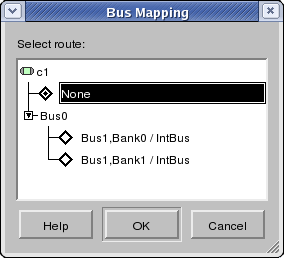
Clicking into the Mapping column of the Design Window hierarchy tab of an architecture model will open a Bus Mapping dialog (shown in Figure 4-25). The Bus Mapping dialog that lists all possible routes for the selected channel. If the dialog's list is empty, there are no possible paths between the given PE end-points and the channel communication can not be implemented over the allocated network. Routes are listed in the form of a tree where each branch corresponds to one hop along the route. For each hop, the names of the data bus, the name of the data bus' sub-protocol (separated by a comma, if any), and optionally the name of the separate interrupt bus (separated by a slash) are shown in the tree.
When opening the dialog, the currently chosen route for the channel is highlighted and pre-selected. Users are able to choose from all possible routes by clicking on and selecting one of the leaves of the tree. Clicking on a leaf item will select and highlight the corresponding route as the list of items from the root of the tree to this leaf. In addition, the dialog contains a ``None'' entry that can be chosen in order to remove any existing explicit bus mapping and switch to implicit routing for that channel.
The Bus Mapping dialog can be closed via Ok and Cancel buttons. Clicking the Ok button will write the selected new route into the design. The hierarchy tab display will be updated after changing the bus mapping to reflect the new mapping for the channel in the Mapping column. On the other hand, clicking the Cancel button will abort the Bus Mapping operation and discard all modifications.
Error/Information Messages: In case of errors when writing the bus mapping information back to the design after pressing the Ok button, an Error dialog is popped up and the bus mapping operation is aborted.
4.6.3. Network Refinement
Network Refinement executes the implementation decisions made in the other Network Exploration tasks by refining the current Architecture Model into an automatically generated Network Model based on and reflecting the decision made during Network Allocation.
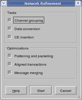
Operation: In order to do refinement, users can select the Main::Synthesis-> Network Refinement menu entry to pop up the Network Refinement dialog. The Network Refinement dialog is shown in Figure 4-26.
In the Network Refinement dialog, users can select whether individual sub-tasks of the network refinement process will be performed or not. By checking or unchecking the check boxes tasks are turned on and off and partially or completely refined models can be generated. By default, all tasks are turned on. The three sub-tasks of network refinement are:
- Channel grouping
which automatically groups and merges sequentially accesses channels over one shared channel.
- Data conversion
which generates implementations of the presentation layer inside PEs for conversion of abstract data types into network bytes.
- CE insertion
which inserts communication elements such as transducers and bridges between PEs and generates necessary additional network protocol implementations inside PEs and CEs.
Optionally, network refinement supports several optimization of the generated output code. Specifically, optimizations apply to the network protocol stacks generated inside the PEs for external bus communication. The purpose of optional protocol stack manipulation is to produce code that is optimized for further hardware or software synthesis in the backend tools. By default, all optimizations are enabled. The three optimizations that can be enabled or disabled during network refinement are:
- Flattening and packeting
which automatically flattens the complete network protocol stack and which performs code fusion to interleave data type conversions with data transfers in order to reduce PE-internal buffer requirements and produce bus-word optimized packeting of data.
- Aligned transactions
which, instead of a tight packing of byte-aligned data (for minimal message size), aligns individual data elements in a message along bus word boundaries and using PE-internal data alignment in order to produce efficient and aligned data conversion and data transfer code optimized for the given PE (at the expense of larger messages and potentially more bus traffic).
- Message merging
which, in order to reduce synchronization resource requirements, automatically packs and merges subsequent transfers into one large message if message transfers directly follow each other over a given channel.
User can then start the network refinement process by clicking the Start button. If users click the Cancel button, the Network Refinement operation will be aborted and cancelled. Either clicking Start or Cancel buttons will close the Network Refinement dialog.
When the network refinement process is finished, the newly generated network model is automatically opened and loaded, and a corresponding new Design Window is created in the Workspace. The new Design Window is automatically activated and raised to the front. In addition, the new network model is automatically added to the current project (see Design Adding, Section 4.2.5) as a child of the architecture model it was generated from.
While the network refinement background tools are running, the majority of the main NE GUI is disabled. However, users can abort/kill execution of the background tools by selecting Main::Synthesis-> Stop. After clicking, the current network refinement background task is aborted.
Error/Information Messages. While the network refinement tool is running, informational (e.g. progress and status reports) and error messages generated by the background tool are displayed in the Output::Refine tab of the Output Window.
If the network refinement background tools abort with an error or are killed via the Main::Synthesis-> Stop menu entry, a corresponding error message will be shown in Output::Refine and an Error dialog will pop up. Upon confirming the error, the remainder of the Network Refinement Operation will be cancelled.
Specifically, the network refinement background tools check for and can produce the following classes of errors:
No top level behavior.
No or invalid network allocation and topology information.
No or invalid CE and bus models in the database.
Unsupported channels or channel connectivity structure in the system architecture at the top level.
Finally, if the design the new model was generated from is not in the project, the new model is not added to the project and an Error dialog to that effect will be popped up.
