4.4. Design-Entity Handling
Design entity handling deals with manipulation of design entities such as behaviors, channels, variables, and channels. In general, design entities are manipulated directly in the currently active Design Window in the Workspace. design entity handling is part of the refinement process and allows the user to perform some typical refinement tasks in a manual fashion. Basically, design entity handling tasks are tasks that do not change the semantics of the design. Rather, they are tasks to apply, for example, cosmetic or syntactic changes like behavior renaming to the design. Specifically, design entity handling consists of the following tasks:
Hierarchy Displaying to toggle between different modes for displaying of the design hierarchy (see Section 4.4.1).
Entity Selection to search for and select entities in the design (see Section 4.4.2).
Entity Isolating to isolate the selected entity from other instances of the same type in the design (see Section 4.4.3).
Entity Wrapping to wrap the selected entity into an additional layer of hierarchy (see Section 4.4.4).
Entity Deletion to delete the selected entity from the design (see Section 4.4.5).
Entity Renaming to rename the selected entity (see Section 4.4.6).
Entity Retyping to change the type of the selected entity (see Section 4.4.7).
Top-Level Selection to select the behavior representing the top level of the system to be designed (see Section 4.4.8).
Design Import to import a design component into the currently active design (see Section 4.4.9).
Decision Import to import design decisions from another opened design into the currently active design (see Section 4.4.10).
4.4.1. Hierarchy Display
Operation: Users can toggle between different modes for displaying the design hierarchy in the Design Window hierarchy tab (Design::Hierarchy). Selecting Main::View->Hierarchy... will open a sub-menu pop-up containing for entries corresponding to the four different display modes:
- Show All
Displays a forest of instantiation hierarchy trees where all uninstantiated behaviors are roots and the complete instantiation tree for all of them is shown.
- Show Testbench
Displays the complete instantiation hierarchy tree for the Main behavior class root only.
- Show Design
Displays the instantiation hierarchy tree only for the root class that is currently the top-level design behavior. This basically shows the current system being designed.
- Show Architecture
Displays the current top-level behavior as the only root class and only displays first-order (direct) children of (instances in) that behavior. This basically shows only the top, system level of the current system being designed.
In addition to switching hierarchy display modes, users can toggle displaying of both variables and channels in the hierarchy tree. Selecting Main::View->Show Variables or Main::View->Show Channels toggles between display of variables and channels in the hierarchy tab of the current Design Window. If channels are displayed, both channel instances and uninstantiated channels are shown in the forest of instantiation hierarchy trees. If variables are displayed, both global variables and variable instances inside behaviors (and optionally channels) are shown in the forest of instantiation hierarchy trees.
4.4.2. Entity Selection
Operation: Users are allowed to select multiple design entities in the different tabs of the Design Window sidebar in order to subsequently apply design entity, refinement or exploration operations simultaneously to all selected entities. Entities in the sidebar tabs can be selected in several different ways:
Clicking on a row in the sidebar tabs of the Design Window will select the row and the corresponding entity. Holding down the mouse button and dragging the mouse over multiple items will select all of them. If the user presses the Ctrl key when clicking on an item, the clicked item gets toggled and all other items are left untouched. And if the user presses the Shift key while clicking on an item, all items between the current item and the clicked item get selected or unselected, depending on the state of the clicked item.
Users can select all items in the currently active sidebar tab of the currently active Design Window by choosing Main::View->Select All. Conversely, all items in the currently active Design Window sidebar tab by choosing Main::View->Deselect All. Finally, choosing Main::View->Select Leaves will only select behaviors and/or channels in the tree/list that are of leaf type (i.e. that do no have child instances).
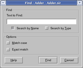
Users can search for and select entities in the currently active sidebar tab of the currently active Design Window by choosing Main::View->Find... The selection will pop-up the Find dialog in which user can choose a name to search for among the list of design entities. The Find dialog is displayed in Figure 4-13.
In the Find dialog, users can enter a regular expression in the Text to find box. By default, only the list entity instance names will be searched and matched against the entered regular expression. However, the user can choose to search instance and/or type names via the corresponding Search by name and Search by type check boxes. Furthermore, through the Match case and Exact match search options check boxes users can select whether entity names are matched against the regular expression in a case-sensitive manner (default is case insensitive) and whether the regular expression has to match the whole entity name, i.e. whether the expression is anchored at the beginning and end of the entity name string (by default, matches against any substring will succeed, too).
Finally, by clicking the Find button, searching and matching will be performed against the list of entities in the currently active Design Window sidebar tab. As a result, all matching entities will be selected. If users click Cancel button, then the action of searching will be cancelled. Either clicking Find or Cancel button will close the Find dialog.
After performing a Main::View->Find.. operation, the first of the found and selected entities will become the active one (whose contents are being displayed in the View Pane). The user can then walk through the list of found and selected entities via the Main::View->Find Next and Main::View->Find Previous main menu entries. With each of these actions, the next or previous entity in the list of matching entities after a search will become the active. The view pane is updated accordingly and the sidebar tab is scrolled to make the entity visible.
4.4.3. Entity Isolating
Mapping a behavior or channel to a PE will automatically map all instances of the entity type to the selected target (see Section 4.5.2). In order to map different instances of the same behavior or channel type to different targets, users can isolate selected design entities before mapping them. Isolating an entity will create a new, unique and exact copy of the behavior/channel and change the type (see Section 4.4.7) of the selected instance to the new type.
Operation: In order to perform entity isolation, users first need to select the corresponding row in the Design::Hierarchy tab. Selecting Design::Hierarchy->Isolate context-menu command will then isolate the selected entity from other instances of the same type.
Error/Information Messages: If isolating the entity in the design leads to an error, an Error dialog with a corresponding error message will pop up and subsequently the operation will be aborted.
 | If the selected entity is already unique in the design (i.e. if there is only one instance of the given type), the isolating operation will silently perform nothing. |
4.4.4. Entity Wrapping
Operation: Users can wrap a design entity into an additional layer of behavior or channel hierarchy. In order to wrapping, users first need to select the corresponding row in the Design::Hierarchy, Design::Behaviors, or Design::Channels tabs. Selecting Design::Hierarchy->Wrap, Design::Behaviors->Wrap or Design::Channels->Wrap context-menu commands will then wrap the selected entity into an additional layer.
Error/Information Messages: If wrapping the entity leads to an error, an Error dialog with a corresponding error message will pop up and subsequently the operation will be aborted.
4.4.5. Entity Deletion
Operation: Users can delete unused design entities from the design. In order to do it, users first need to select the corresponding row in Design::Hierarchy, Design::Behaviors, or Design::Channels tabs. Selecting Design::Hierarchy->Delete, Design::Behaviors->Delete or Design::Channels->Delete context-menu commands will then delete the selected entity from the design.
Error/Information Messages: If deleting the entity in the design leads to an error (e.g. if the entity is used by another entity, i.e. if some part of the design depends on that entity), an Error dialog with a corresponding error message will pop up and subsequently the operation will be aborted.
4.4.6. Entity Renaming
Operation: The names of design entities including behaviors, behavior instances, channels, channel instances, variables, and ports are displayed in Name column of the Design Window tabs. Users can change these names of entities. In order to do it, users first select the corresponding row in Design::Hierarchy, Design::Behaviors or Design::Channels tabs. Selecting Design::Hierarchy->Rename, Design::Behaviors->Rename, or Design::Channels->Rename context-menu commands will then allow users to edit the names directly in the cell by opening a corresponding text edit box in place. Renaming can be aborted by pressing the Esc key. Pressing Enter accepts the newly entered name and renames the entity in the design.
Error/Information Messages: If renaming the entity in the design leads to an error (e.g. if an entity with the same name already exists), an Error dialog with a corresponding error message will pop up and subsequently the operation will be aborted.
4.4.7. Entity Retyping
Operation: Users can change the type of design entity instances including variable, channel and behavior instances that are displayed in the Type column of the Design Window hierarchy tab. In order to do it, users first need to select the corresponding row in the Design::Hierarchy tab. Selecting the Design::Hierarchy->Change Type context-menu command will then allow users to chose a type for the instance entity from a list of compatible types directly in the cell by opening a drop-down combo box with entries for all compatible types in place. Compatibility in SpecC is defined by a match in the list of port types and the list of implemented interfaces, e.g. two behaviors are compatible if they have the same list of ports in terms of order and type of ports. Users can choose any of the offered types from the drop-down list. Selecting a new type will then change the type of the instance entity in the design.
Error/Information Messages: If retyping of the entity in the design leads to an error, an Error dialog with a corresponding error message will pop up and subsequently the operation will be aborted.
4.4.8. Top-Level Selection
Users can select the top-level behavior which represents the system design to be implemented. All the children of the top-level behavior are considered to be part of the system design. On the other hand, all the parents/siblings of the top-level behavior are considered to belong to the testbench outside of the actual design.
Operation: Users first select the desired behavior by clicking its row in the Design::Hierarchy or Design::Behaviors tabs. Then, users set the selected behavior as the top-level behavior by selecting the Design::Hierarchy->Set As Top-Level or Design::Behaviors->Set As Top-Level commands in the context-menu for the respective behavior.
After selection, the instantiation hierarchy tree with the current top-level behavior at its root will be visually emphasized/highlighted (through use of an italic font for entity texts) in the Design Window's hierarchy tab (Design::Hierarchy).
Error/Information Messages: All allocation information is stored in the design as annotations at the top-level design behavior (see Section 4.5.1, Section 4.6.1, etc.). When switching the top-level from one behavior to another, if an allocation exists at the current behavior, an Information dialog is popped up querying the user whether he wants to copy the existing allocation over to the new top-level behavior. If the user accepts the recommendation and if then an allocation already exists at the new top-level behavior, another Information dialog is popped up querying the user whether he wants to overwrite the allocation information at the new top-level behavior. If the user declines the recommendation, the previous allocation at the new top-level behavior is kept.
4.4.9. Design Import
Operation: Users can import an existing design file on disk into a currently opened and loaded design. Importing a design will merge the design's contents into the currently opened design (equivalent to a SpecC import statement). All the design entities in the imported files can then be used in the current design. For example, in order to do plug-and-play of behaviors, users can replace a behavior in a design with an imported compatible behavior (see Section 4.4.7 for the Changing Type action).
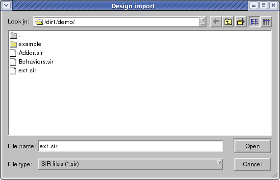
In order to import a design users should first active the target Design Window in the Workspace and then select Main::Synthesis->Import Design.... The selection will pop up the Design Import dialog in which users can select and choose an existing design file on disk to open and import into the currently active Design Window. The Design Import dialog is shown in Figure 4-14.
In the Design Import dialog, users should first specify the directory of the file in Look in box. The content of the directory will be automatically displayed in the display box in the center. The file type defaults to SIR files (*.sir). All the files with the specified type will be displayed in the display box. Users then further select the file name in the File name box. Finally, by clicking the Open button, the design file with the specified name will be imported. If users click the Cancel button, then the action of Design Import will be cancelled. Either clicking Open or Cancel button will close the Design Import dialog.
4.4.10. Decision Import
In order to take over implementation decisions from a previously done design into a new design, SCE allows to import design decisions from one design into another. With this functionality, previously made design decisions can easily be transfered to a new design as a starting point for exploration.
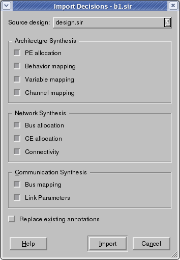
Operation: Users can import design decisions from any currently opened and loaded design into the currently active design by selecting the main menu command Main::Synthesis->Import Decisions. As a result, the Import Decisions dialog will be popped up as shown in Figure 4-14.
First, in order to select a design from which decisions are imported, users select the name of the source design in the Source design drop-down box. The combo box contains all the names of currently opened Design Windows except for the currently active one. Users select one design from them as the source design.
Secondly, users can select decisions which will be imported to the current design. Users do it by checking the selection items as follows:
- PE Allocation
Copies the allocated PEs/memories from the source design to the currently active design. For all behaviors in the source design, PE allocation annotations are copied to the behavior (if any) with the same name in the target design.
- Behavior Mapping
Copies behavior mapping information from the source design to the currently active design. For all behaviors in the source design, PE mapping annotations are copied to the behavior (if any) with the same name in the target design.
- Variable Mapping
Copies variable mapping information from the source design to the currently active design. For all variable definitions in all behaviors in the source design, PE mapping annotations are copied to the variable (if any) with the same name in the behavior (if any) with the same name in the target design.
- Channel Mapping
Copies channel mapping information from the source design to the currently active design. For all channel instances in all behaviors in the source design, PE mapping annotations are copied to the channel instance (if any) with the same name in the behavior (if any) with the same name in the target design.
- Bus Allocation
Copies the allocated busses from the source design to the currently active design. For all behaviors in the source design, bus allocation annotations are copied to the behavior (if any) with the same name in the target design.
- CE Allocation
Copies the allocated CEs from the source design to the currently active design. For all behaviors in the source design, CE allocation annotations are copied to the behavior (if any) with the same name in the target design.
- Connectivity
Copies the network topology connectivity from the source design to the currently active design. For all behaviors in the source design, network connectivity annotations are copied to the behavior (if any) with the same name in the target design.
- Bus mapping
Copies the bus segment mapping information from the source design to the currently active design. For all channel instances in all behaviors in the source design, bus mapping annotations are copied to the channel instance (if any) with the same name in the behavior (if any) with the same name in the target design.
- Link parameters
Copies the address and interrupt assignments from the source design to the currently active design. For all channel instances in all behaviors in the source design, address and interrupt assignment annotations are copied to the channel instance (if any) with the same name in the behavior (if any) with the same name in the target design.
There are two buttons on the Import Decisions dialog: Import and Cancel. By clicking the Import button, the design decisions of the selected items are imported to the selected design from the source design. If users clicks the Cancel button, the action of decision importing will be aborted and cancelled. Either clicking Import or Cancel button will close the Import Decisions dialog.
Error/Information Messages: Decision importing requires reading and writing of annotations in the designs. In case of errors (e.g. wrong annotation format) upon pressing the Import button, an Error dialog will be popped up and the decision importing operation will be aborted.


