4.4. RTL Scheduling and Binding
The most important steps during RTL synthesis are scheduling and binding. Scheduling is to decide the start time of operations in a design. Binding is to map operations to functional units (function binding) and to map variables to storage units (storage binding), and to map data transfers to buses (connection binding). Due to the interdependence of scheduling and binding, the order of these steps may be interchanged to get better design.
In our RTL design methodology, we provide manual scheduling and binding for the designers to make decision for scheduling and binding. But manual scheduling and binding takes too much time for the designers to do and is tedious and error-prone task. We will provide automatic scheduling and binding tools by RTL plugins.
Note that if reader is not interested in how to do manual scheduling and binding, she or he can skip this section to go directly Section 4.4.2.
4.4.1. Schedule and bind manually (optional)
SCE allows for the designer to manually schedule and bind the operations. However, this is a tedious task and can be done by automated tools. To perform automatic scheduling and binding, the designer can skip the manual step and go directly to Section 4.4.2.
If RTL Scheduling & Binding window is not open yet, we have to open it again by selecting Synthesis->Schedule & Bind RTL from the menu bar. Choose the behavior "Build_Code_FSMD" from the hierarchy.
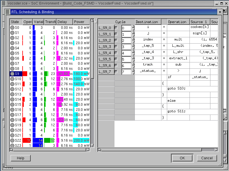
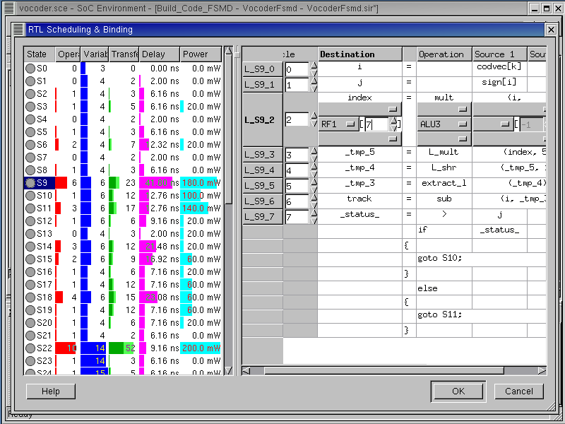
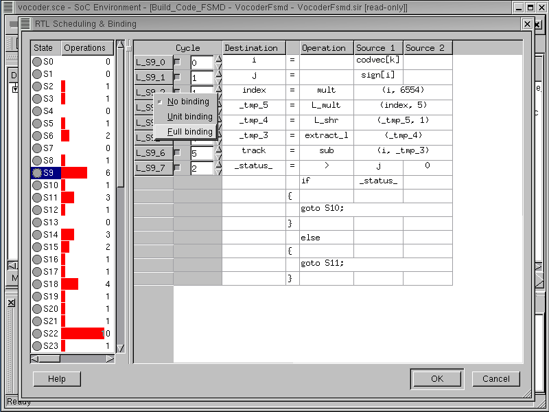
we will show how to specify control step for each statement in a state. In RTL Scheduling and Binding window, we select "S9" to do manual scheduling and binding. In the right side panel of the RTL Scheduling & Binding window, left click on the right side of the label "L_S9_0". This activates the Cycle column for "L_S9_0". We can specify the control step for it. In this way, we can specify control step for all statement in the state S9.
Note that if reader is not interested in how to do manual scheduling and binding, she or he can skip this section to go directly Section 4.4.2.
4.4.1.1. Schedule and bind manually (optional) (cont'd)
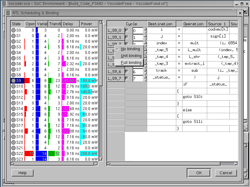
To perform manual binding for operations in the state S9, right click on Label, "L_S9_2". It will pop up a menu for the binding options. Select Full binding.
4.4.1.2. Schedule and bind manually (optional) (cont'd)
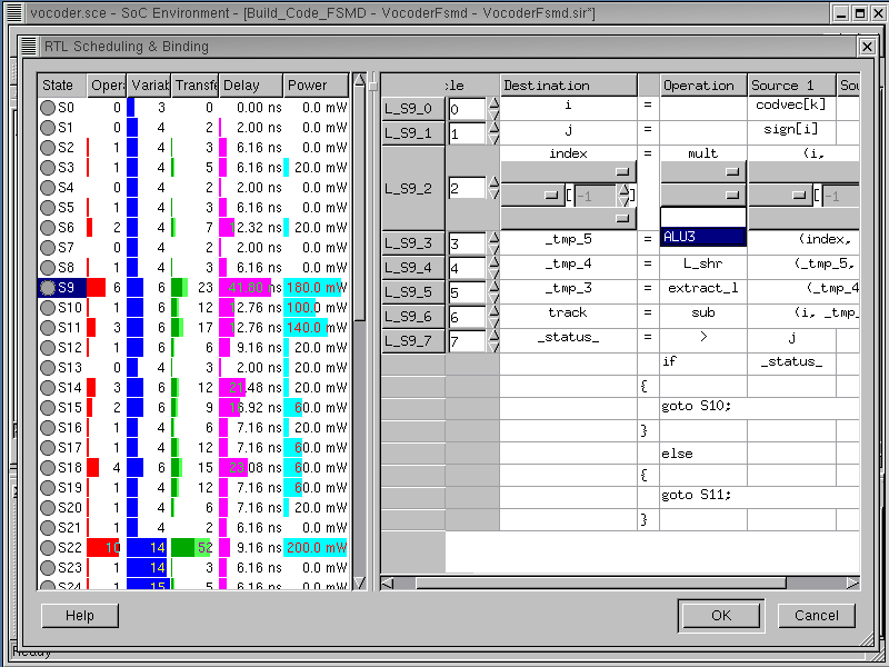
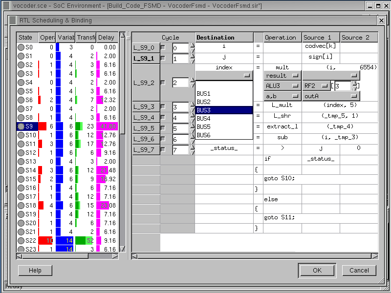
Each column in a statement in right side of the window is now expanded to allow manual binding. We will bind a function call, mult (Operation column), to "ALU3". To do so, left click on 2nd blank row of the Operation column. Then pull-down menu pops up and shows all functional units which can perform function call mult. In this case, one possible functional unit, "ALU3" is shown in the pull-down menu.
4.4.1.3. Schedule and bind manually (optional) (cont'd)
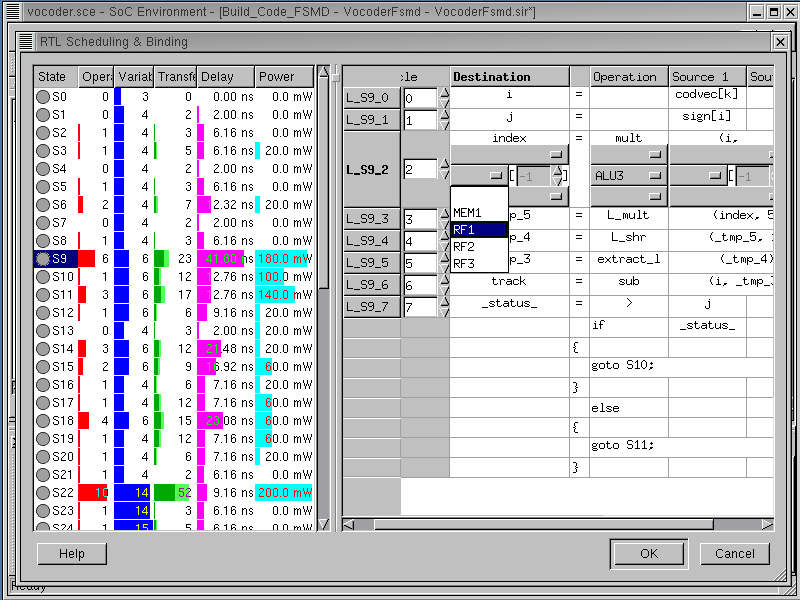
We will bind a target variable index (Destination column) to RF1[7]. To do so, left click on 2nd blank row of the Destination column. Then pull-down menu pops up and shows all storage units In this case, four storage units such as "MEM1", "RF1", "RF2" and "RF3" are shown in the pull-down menu. Click on "RF1" to select "RF1".
4.4.1.4. Schedule and bind manually (optional) (cont'd)
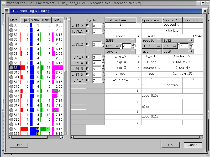
For storage unit binding, the address of the variable in the memory should be specified. Left click on right side of the 2nd row of Destination column. Specify the memory address to 7 for variable "index". The -1 in address field for a memory is default value which means that the address for the memory is not bound yet.
4.4.1.5. Schedule and bind manually (optional) (cont'd)
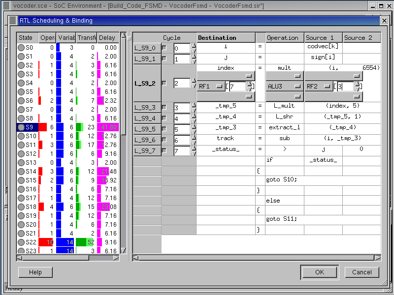
Likewise, source variable, "i" is bound to RF2[3].
4.4.1.6. Schedule and bind manually (optional) (cont'd)

So for, we performed functional unit and storage unit binding. We can specify more information on binding, such as ports of the functional unit and storage unit and buses for data transfers. For the output port binding of the functional unit, left click on the 1st row of the Operation column which will show all output ports in ALU3 unit.
4.4.1.7. Schedule and bind manually (optional) (cont'd)
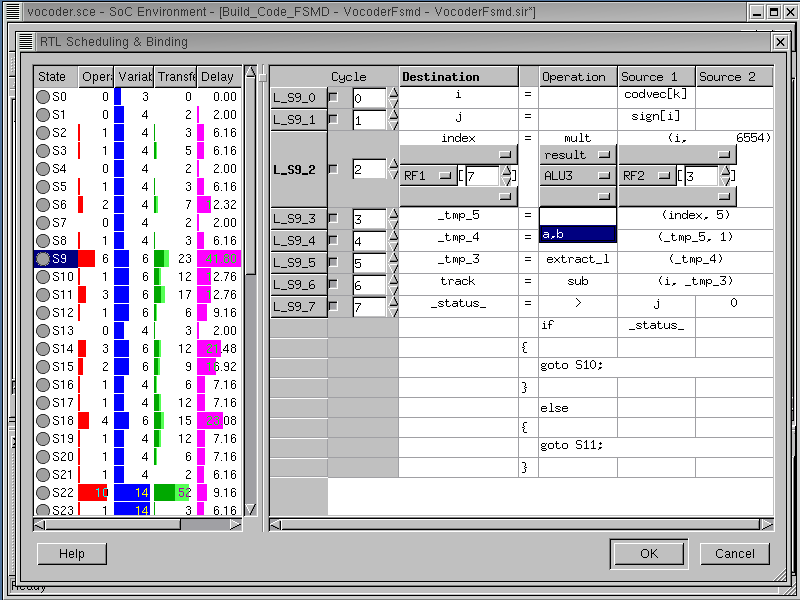
For the input port binding of the functional unit, left click on the 3rd row of the Operation column which will shows all input ports in ALU3 unit.
4.4.1.8. Schedule and bind manually (optional) (cont'd)
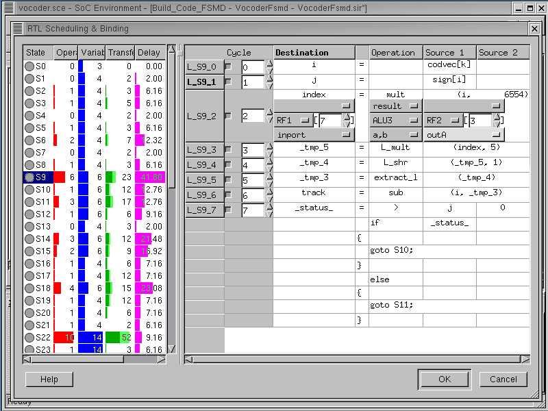
In this way, we can select write port for the write storage unit (RF1[7]) and read port for the read storage unit (RF2[3]).
4.4.1.9. Schedule and bind manually (optional) (cont'd)
For the bus binding, left click on the 1st row of the Destination column which shows all allocated buses. For target variable "index", "BUS3" is selected for write.
4.4.1.10. Schedule and bind manually (optional) (cont'd)
In this way, we can perform all binding in the RTL Scheduling and Binding window. However, manual binding takes too much time and is an error-prone task. An easier alternative is to use automatic scheduling and binding tools.
Left click on Cancel. Otherwise, the scheduling and binding information will be inserted and then used by automatic scheduling and binding tools. It may generate an incorrect RTL model.
4.4.2. Schedule and bind automatically
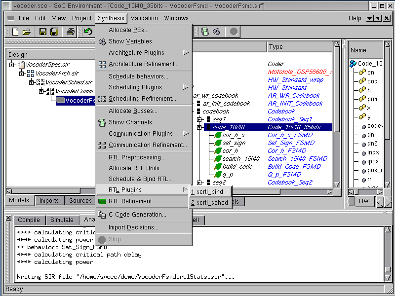
As already discussed, manual scheduling and binding takes too much time for a designer to do and also is an error-prone task. We will now perform scheduling and binding with the help of tools which implement scheduling and binding algorithms. In our design flow, an automatic decision making tool for system-level design is called a "Plug in". For RTL scheduling and binding, we call "RTL Plugins" by selecting Synthesis->RTL PlugIns->scrtl_bind from the menu bar. Before that, we have to select a behavior "Code_10i40_35bits".
4.4.2.1. Schedule and bind automatically (cont'd)
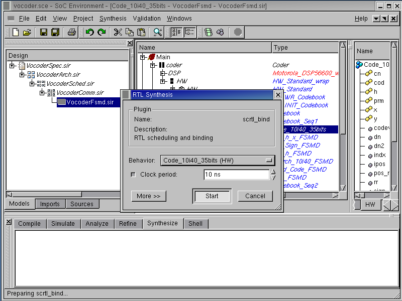
An RTL Synthesis dialog box pops up. In the middle of the dialog box, a pull-down list is available to select the desired behavior. The default behavior in the list is the one that is highlighted in the behavior hierarchy tree. For our demo, select behavior "Code_10i40_35bits (HW)" from the list. By default, the clock period of the behavior is 10 ns. Now click on Start to begin "scrtl_bind".
4.4.2.2. Schedule and bind automatically (cont'd)
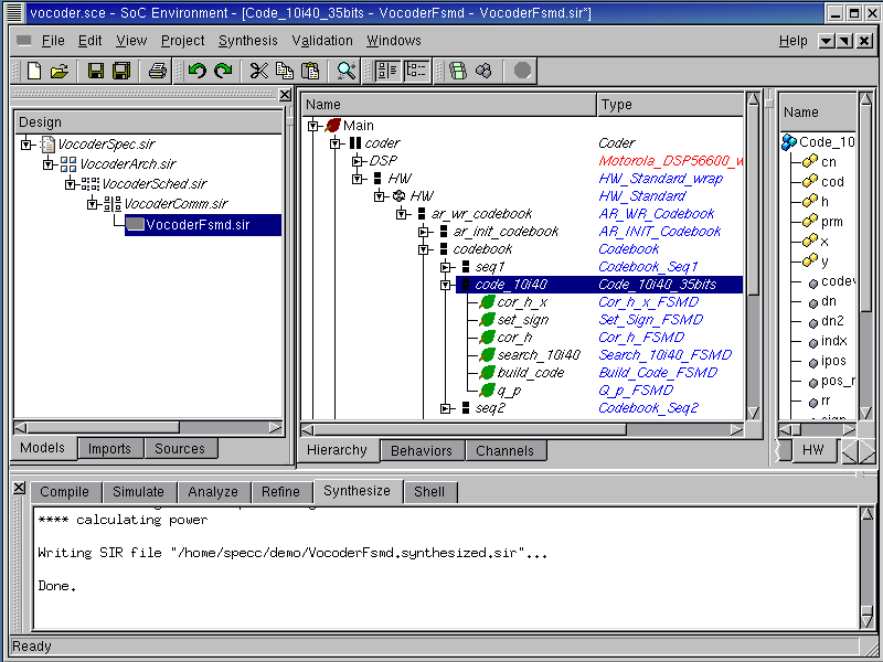
Note that "scrtl_bind" annotates scheduling and binding information into SFSMDs for all 6 sub-behaviors of the behavior "Code_10i40_35bits", as seen in the logging window. The tool finally generates the SFSMD model for the behavior "Code_10i40_35bits".
4.4.2.3. Browse scheduling and binding result (optional)
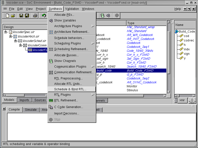
To check the scheduling and binding result generated by "scrtl_bind", we have to go over to RTL Scheduling & Binding window again by selecting Synthesis->RTL Scheduling & Binding from the menu bar. Before that, we have to select a behavior "Build_Code_FSMD".
If the reader is not interested in details of the scheduling and binding results, she or he skips this section and go directly Section 4.5.
4.4.2.4. Browse scheduling and binding result (optional) (cont'd)
In the RTL scheduling and Binding window, Cycle column shows the control step of each statement. To see the binding information, we activate Full binding by selecting Full binding in the binding pop-up menu.
4.4.2.5. Browse scheduling and binding result (optional) (cont'd)
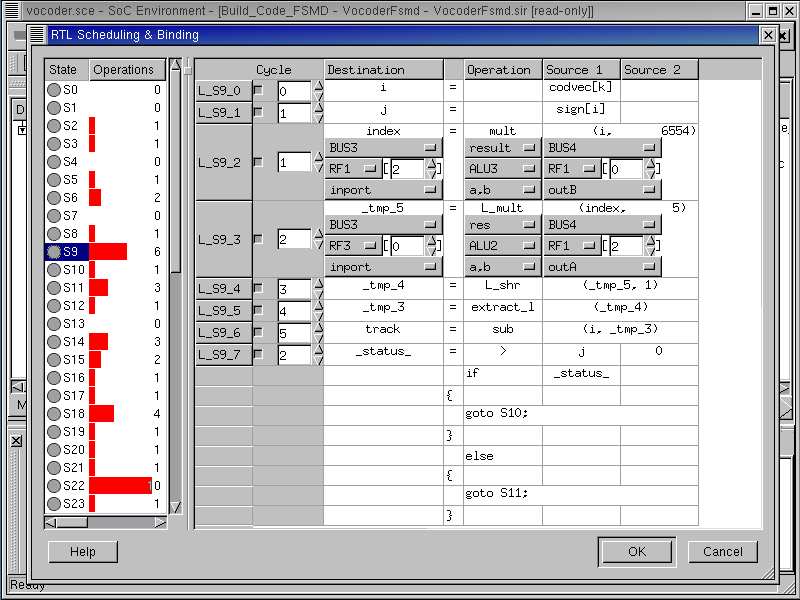
This is the scheduling and binding result for the L_S9_2 and L_S9_3 statement. The statement L_S9_2 is scheduled control step 1 relative to the start of state S9. The function call "mult" is performed by ALU3. The variable "index" in statement L_S9_2 is bound to RF1[2] which stores the result of the function call "mult" through the bus "BUS3".
Left click on Cancel.