4.3. RTL Allocation
RTL allocation is one of important steps for custom hardware design. It is to select number of RTL components for the design, while meeting various constraints. For RTL allocation, we need to get a statistical information on the design.
The statistical information contains the number of operations for functional unit allocation, the number of live variables for storage unit allocation and the number of data transfers for bus allocation and the number of operations in the critical path in each state. These kinds of information can be obtained by performing RTL analysis.
4.3.1. Allocate functional units
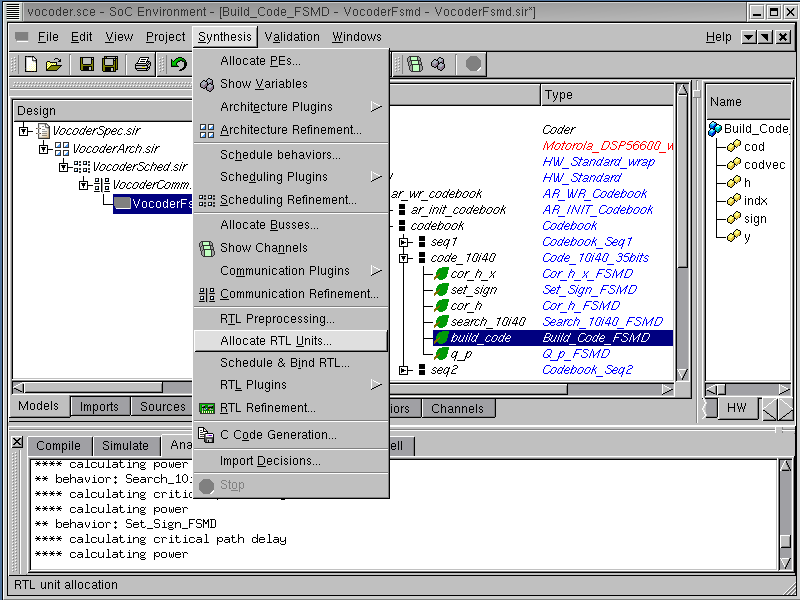
After we produce a valid SFSMD model during preprocessing step, the next step is to allocate RTL components for HW part of the system. The allocation will be guided by RTL statistical information. To perform the allocation, select Synthesis->Allocate RTL Units from the menu bar.
4.3.1.1. Allocate functional units (cont'd)
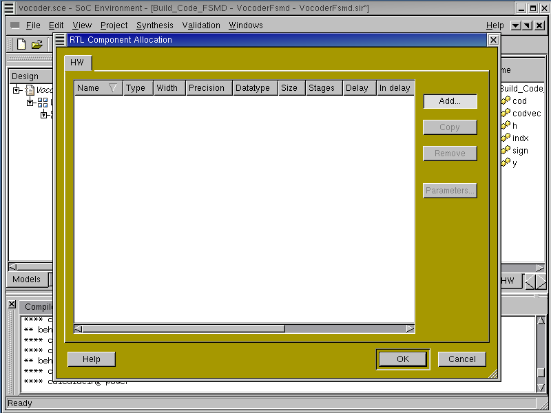
An RTL allocation window pops up just like for components and busses. left click on Add to see the include units from the database into the design.
4.3.1.2. Allocate functional units (cont'd)
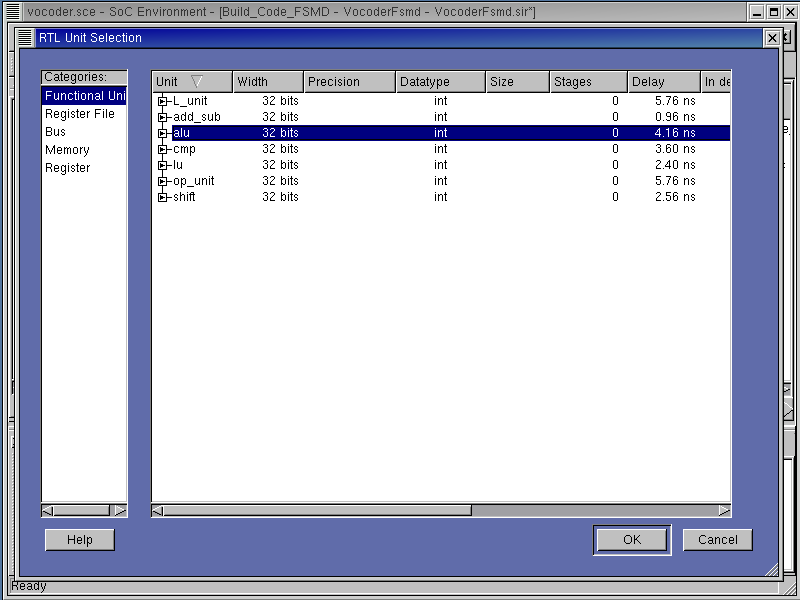
A RTL Unit Selection window pops up for RTL unit selection. There are various categories for the RTL components listed on the left-most column. Left click on "Functional Unit" to see the functional units and their parameters in the right-most column. In this tutorial, we will select 3 functional units: "L_unit" and "op_unit" for saturated arithmetic operations and "alu" for the other operations. To select an alu, left click on "alu" and click on OK to add it to RTL Unit Selection window.
4.3.1.3. Allocate functional units (cont'd)
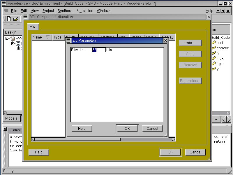
A new property box for the alu component pops up and shows the configurable parameters. In case of alu, bit width is the configurable parameter. Left click on OK to use the default value of 32 bits.
4.3.1.4. Allocate functional units (cont'd)

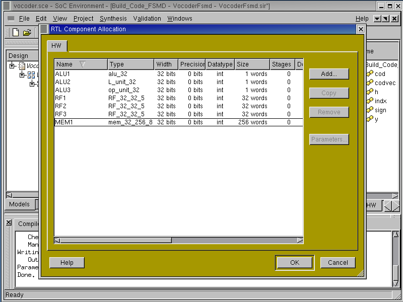
The allocated alu component will be shown in the RTL Component Allocation window. Left click on Name column of the allocated alu to rename it to ALU1.
We may repeat the last procedure to allocate more RTL components from the database.
4.3.1.5. Allocate functional units (cont'd)
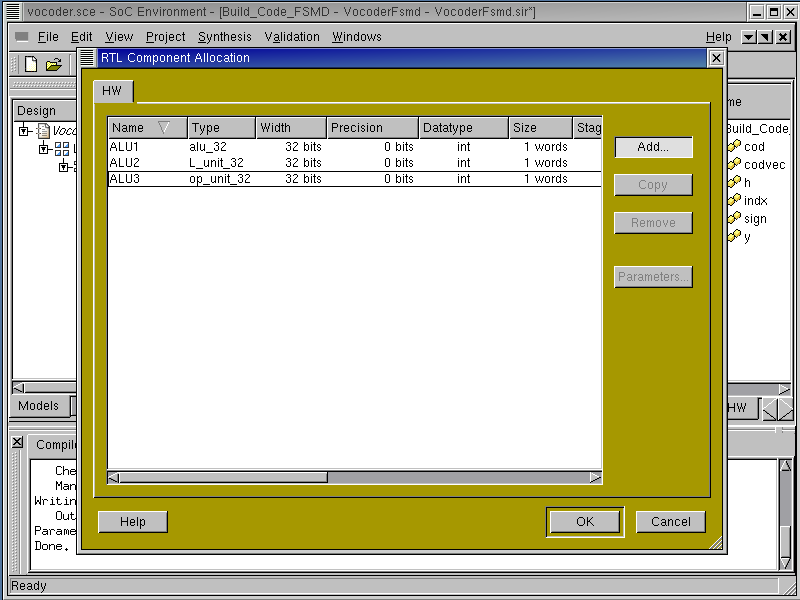
In this way, we can allocate an "L_unit" and an "op_unit" and rename them to ALU2 and ALU3 respectively.
All desirable functional units for hardware implementation have now been selected. However, we also need storage units like register files and memory. Left click on Add.
4.3.2. Allocate storage units
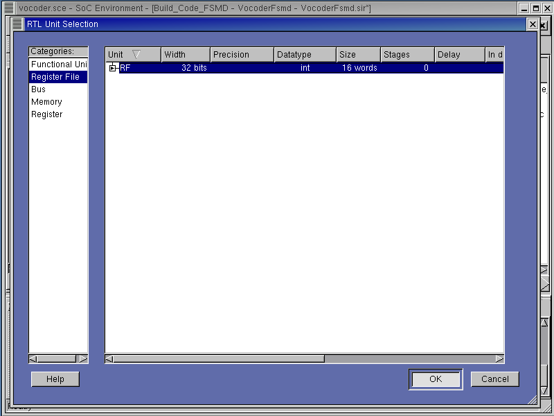
Left click on "Register File" to see the various register files and their properties. Left click on "RF" to select register file and click on OK to add it to RTL Unit Selection window.
4.3.2.1. Allocate storage units (cont'd)
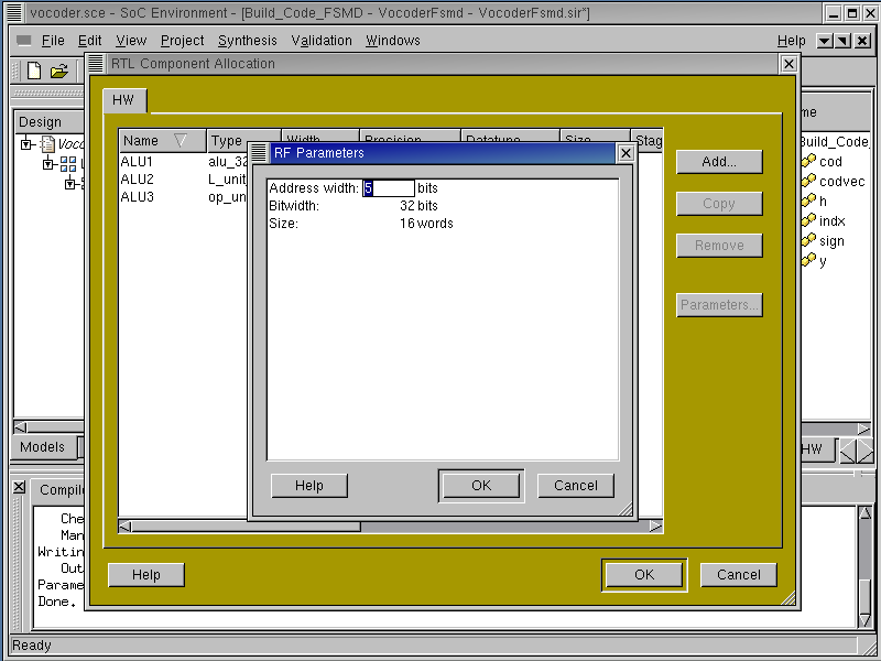
A new property box for RF component pops up and shows the configurable parameters. In case of RF, address width and size of register file as well as bit width are the configurable parameters. Left click on "Address width" to change 4 bits to 5 bits.
4.3.2.2. Allocate storage units (cont'd)

Since the address width is changed to 5 bits, the allowed address space is 32 words. Left click on size to change 16 words to 32 words.
Left click on OK to add RF to RTL allocation.
4.3.2.3. Allocate storage units (cont'd)

The selected RF component will be shown in the RTL Component Allocation window. Left click on Name column of the allocated RF to rename it to RF1.
4.3.2.4. Allocate storage units (cont'd)
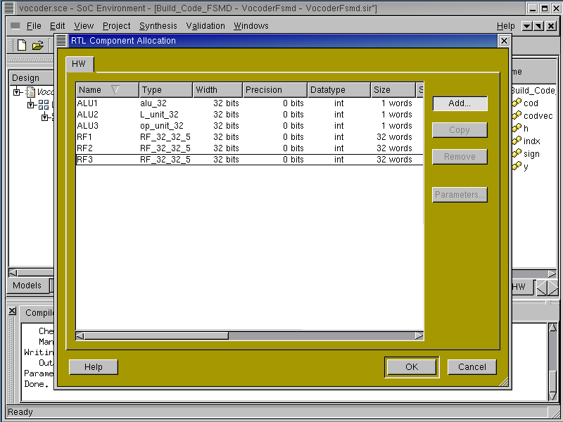
For the purpose of this design we will need 3 register files to perform RTL synthesis. To add more register files in the allocation table, simply Left click on Copy by 2 times. This is a useful way to replicate components for large sized allocations.
Now, we have allocated 3 register files. In the similar way, we can allocate a memory component.
4.3.2.5. Allocate storage units (cont'd)
In the "Memory" category, we select the "mem" type memory. Its size is 256 words, and then its address width is 8 bits. Also its bit width is 32 bits.
We are now done with storage unit allocation and we have to allocate busses for data transfers between storage units and functional units. Left click on Add to add more RTL components.
4.3.3. Allocate buses
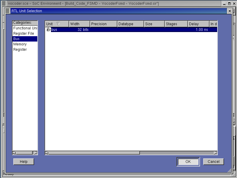
Left click on "Bus" to see its properties in the left-most column. Left click on "bus" to select the bus and press OK.
4.3.3.1. Allocate buses (cont'd)

A new property box for bus component pops up and shows the configurable parameters. In case of bus, bit width is the configurable parameter. Left click on OK to add bus to RTL allocation.
4.3.3.2. Allocate buses (cont'd)
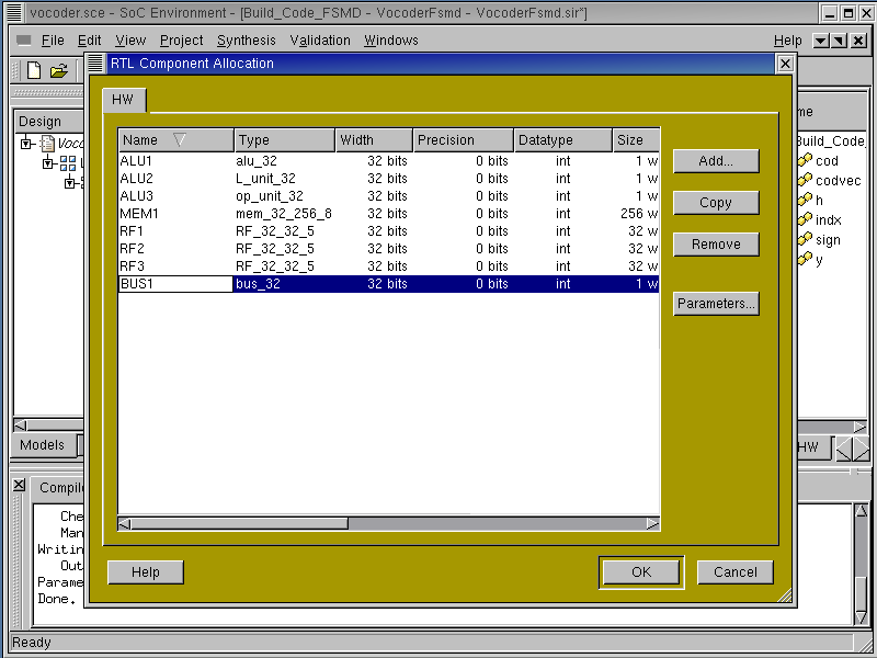
The selected bus component will be shown in the RTL Component Allocation window. Left click on Name column of the allocated bus to rename it to BUS1.
4.3.3.3. Allocate buses (cont'd)
For the purpose of this design we will need 6 buses to perform RTL synthesis. To add more buses in the allocation table, simply left click on Copy by 5 times. This is a useful way to replicate components for large sized allocations.
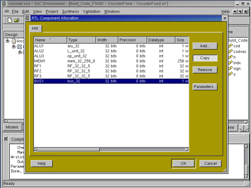
4.3.3.4. Allocate buses (cont'd)
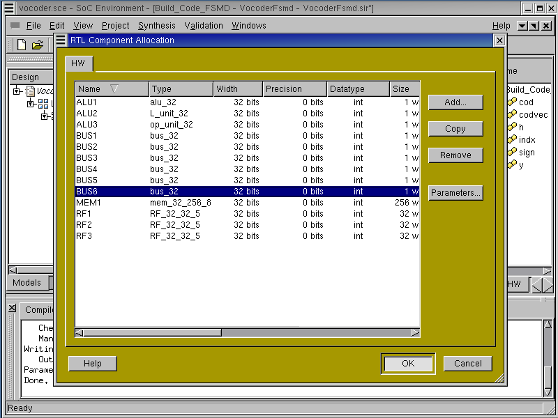
We are now done with RTL component allocation. Left click on OK to save the allocation information in the model.
4.3.3.5. Analyze allocated SFSMD model
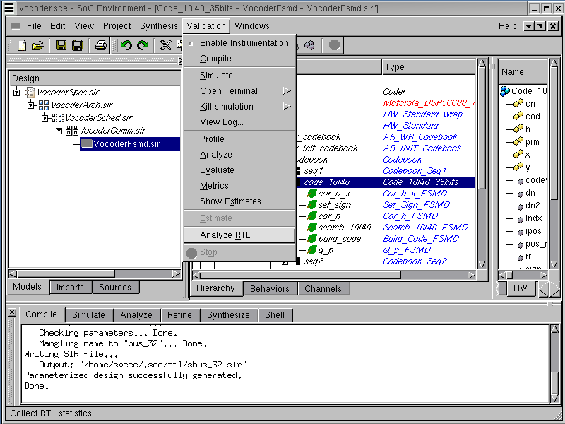
Before scheduling and binding, we may check how RTL allocation will affect performance, area, and power in the design. To do so, we can go over RTL analysis again. we select the behavior "Code_10i40_35bits", for which we want to get the statistical information. The RTL analysis is performed by selecting Validation->Analyze RTL from the menu bar.
4.3.3.6. Analyze allocated SFSMD model (cont'd)
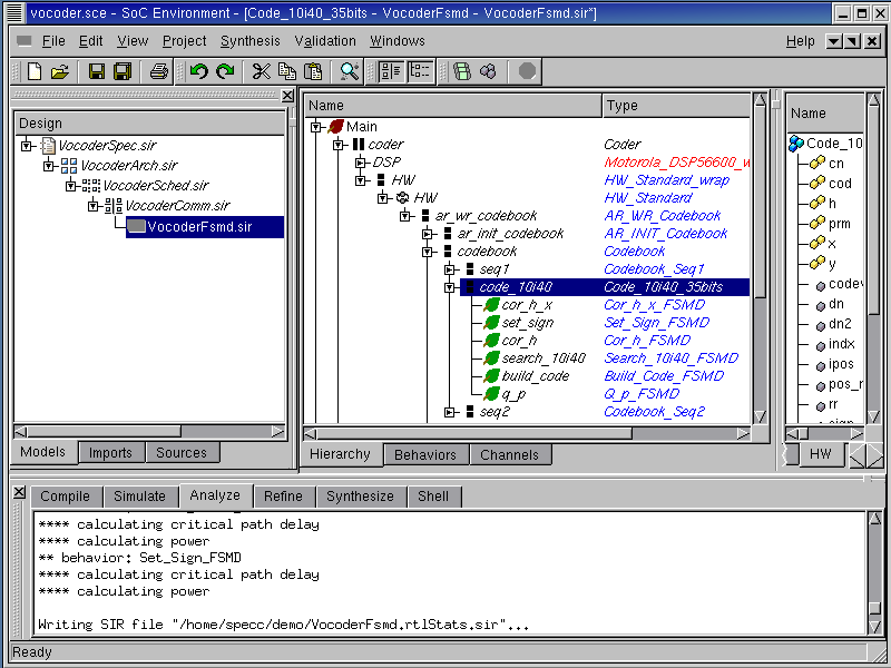
RTL analysis tool will go over all sub-behaviors in behavior "Code_10i40_35bits", and generate the more accurate statistical information with the help of allocation information.
4.3.3.7. Analyze allocated SFSMD model (cont'd)

Now, we will look at RTL analysis result because we allocated RTL components for the design by selecting Synthesis->Schedule & Bind RTL from the menu bar. Choose the behavior "Build_Code_FSMD" from the hierarchy.
4.3.3.8. Analyze allocated SFSMD model (cont'd)
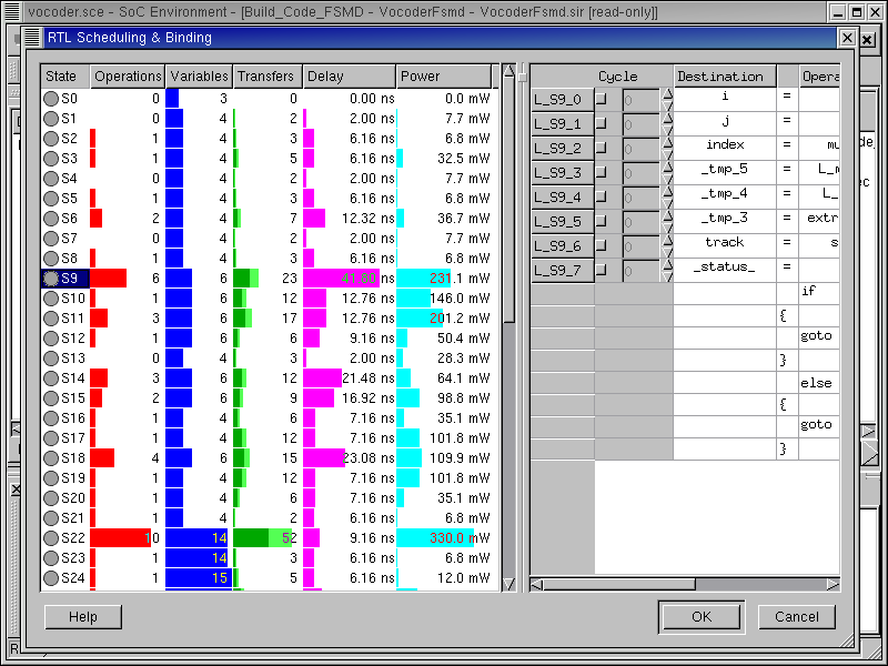
The RTL Scheduling & Binding window pops up showing all the states in the behavior "Build_Code_FSMD". In the left-most columns, we can see the estimated delay and powers for each state. For example, state S9 will take 41.80 ns to execute and consume 180.0 mW.