Chapter 4. Custom Hardware Design
4.1. Overview
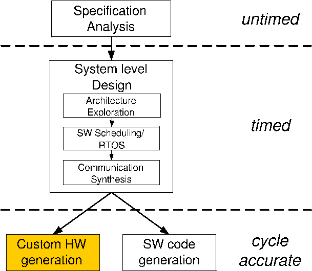
In this chapter, we look at custom HW generation step as highlighted in Figure 4-1. The bus functional model derived from the system level design phase must now be used to generate custom hardware for HW components. In this phase of RTL synthesis, our goal is to generate an RTL model that can be fed into industry standard synthesis tools. In this chapter, we will deal exclusively with behaviors mapped to HW components and show how a cycle accurate model is derived from a bus functional one.
First, super finite state machine with data (SFSMD) will be generated from the communication model. Each super state in SFSMD corresponds to a basic block in communication model and will have only data flow information. The control flow information will be described among super states of the behavior. Super states in SFSMD will be split into multiple states during RTL synthesis.
Second, the RTL units for the custom hardware are allocated. To get some information like number of operations, number of variables and number of data transfers in the SFSMD for the RTL allocation, the designer has to run RTL analysis tool.
Third, scheduling and binding is done by designer or by tools. The scheduling and binding information will be inserted into the SFSMD model.
Finally, the SFSMD model with scheduling and binding information is refined into a cycle-accurate FSMD model by RTL refinement tool. The refinement tool will also gererate a cycle accurate model in hardware description languages like Verilog and Handel-C. The cycle accurate model in Verilog HDL can be used as input to commercial logic synthesis tools like Synopsys Design Compiler. We also generate the cycle-accurate model in Handel-C which can be fed into Celoxica Design Kit.