3.4. Communication Synthesis
Communication synthesis is the second part of the system level synthesis process. It refines the abstract communication between components in the architecture model. Specifically, the communication with variable channels is refined into an actual implementation over wires of the system bus. The steps involved in this process are as follows.
We begin with allocation of system buses and selection of bus protocols. A set of system buses is selected out of the bus library and the connectivity of the components with system buses is defined. In other words, we determine a bus architecture for our design.
This is followed by grouping of abstract variable channels. The communication between system components has to be implemented with busses instead of variable channels. Thus these channels are grouped and assigned to the chosen system busses. Once this is done, the automatic refinement tool produces the required bus drivers for each component. It also divides variables into slices whose size is the same as width of the data bus. Therefore that each slice can be sent or received using the bus protocol. The entire variable is sent or received using multiple transfers of these slices.
3.4.1. Select bus protocols
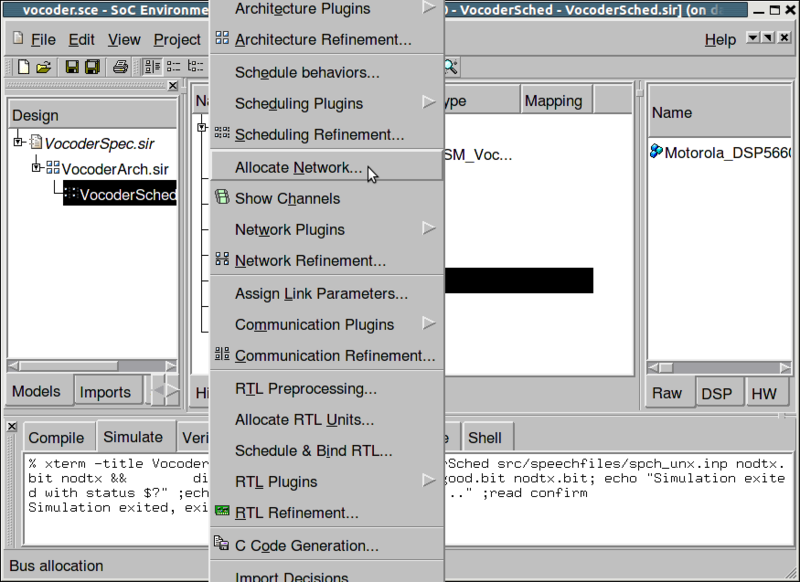
As explained earlier, we begin by selecting a suitable bus for our system. Note that in the presence of only two components, one bus would suffice. However, in general the user may select multiple buses if the need arises. Bus allocation is done by selecting Synthesis->Allocate Network from the menu bar.
3.4.1.1. Select bus protocols (cont'd)
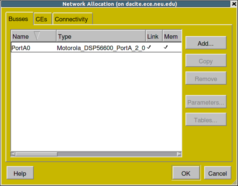
A Bus Allocation window pops up showing the bus allocation table. In the network allocation window there will be three tabs: Busses, CEs, and Connectivity. In the Busses tab, by default the "Motorola_DSP56600_PortA" bus will be present. This is the required bus. Rename this bus to "Bus0" by left clicking "Port0" and typing "Bus0." Note that the architecture chosen for the design has an impact on the selection of busses. More often that not, the primary component in the design dictates the bus selection process. In this case, we have a DSP with an associated bus. It makes sense for the designer to select that bus to avoid going through the overhead of generating a custom bus adapter. Click the Connectivity tab to allocate the bus.
3.4.1.2. Select bus protocols (cont'd)
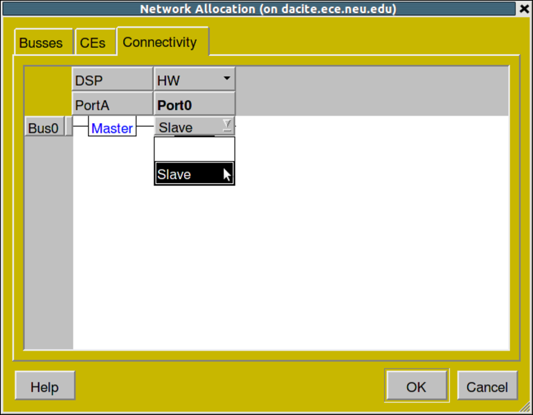
The Connectivity tab shows that the hardware element has one port, PortA0, available. Set PortA0 of "HW" as "Slave on "Bus0" by clicking the menu under "HW" "Port0" and selecting slave. Click OK to confirm your changes.
3.4.2. Map channels to buses
Once the bus allocation has been done, we need to group the channels of the architecture model and assign them to the system buses. Recall that in the architecture model, we had communication between components with abstract variable channels. We now have to assign those variable channels to the system bus.
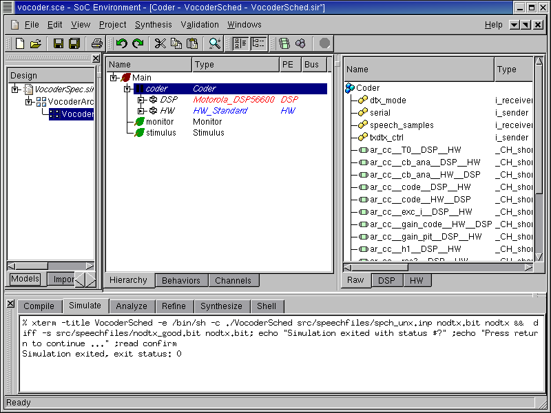
Expand the design hierarchy window and scroll to the right to find a new column entry Bus.
3.4.2.1. Map channels to buses (cont'd)
Like component mapping, bus mapping may be done by assigning variable channels to buses. However, to speed things, we may assign the top level component to our system bus. Since we have only one system bus, all the channels will be mapped to it. This is done by left clicking in the row for the "Coder" behavior under the bus column. Select the default "Bus0" and press RETURN.
3.4.3. Generate communication model
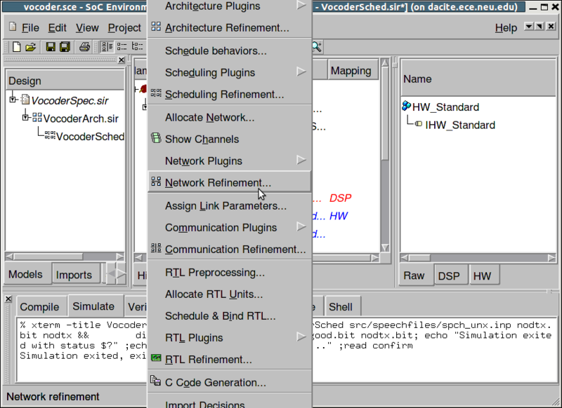
Now that we have completed bus allocation and mapping, we may proceed with network refinement. Like architecture refinement, this process automatically generates a new model that reflects our desired bus architecture. To invoke the network refinement tool, select Synthesis->Network Refinement from the menu bar.
3.4.3.1. Generate communication model (cont'd)
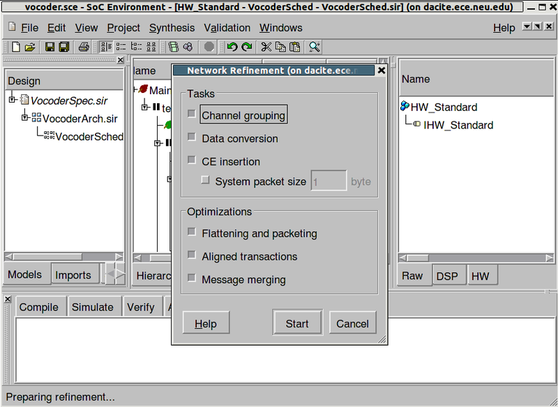
A new window pops up giving the user the option to perform various stages of the refinement. The user may choose to partially refine the model without actually inserting the bus, and only selecting the channel refinement phase. This way, he can play around with different channel partitions. Likewise, the user might want to play around with different bus protocols while avoiding "Inlining" them into components. This way he can plug and play with different protocols before generating the final inlined model. By default all the stages are performed to produce the final communication refinement. Since we have only one bus, and hence a default mapping, we opt for all three stages and left click on Start to proceed.
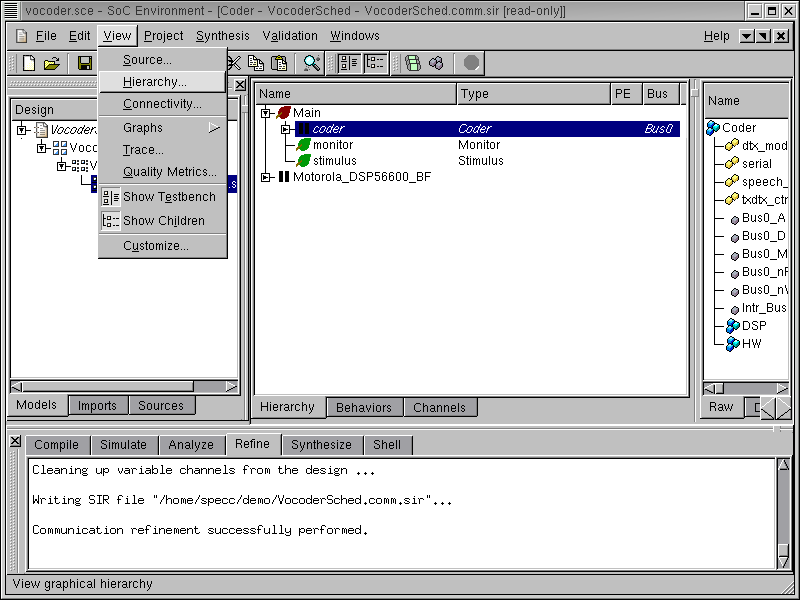
3.4.3.2. Generate communication model (cont'd)
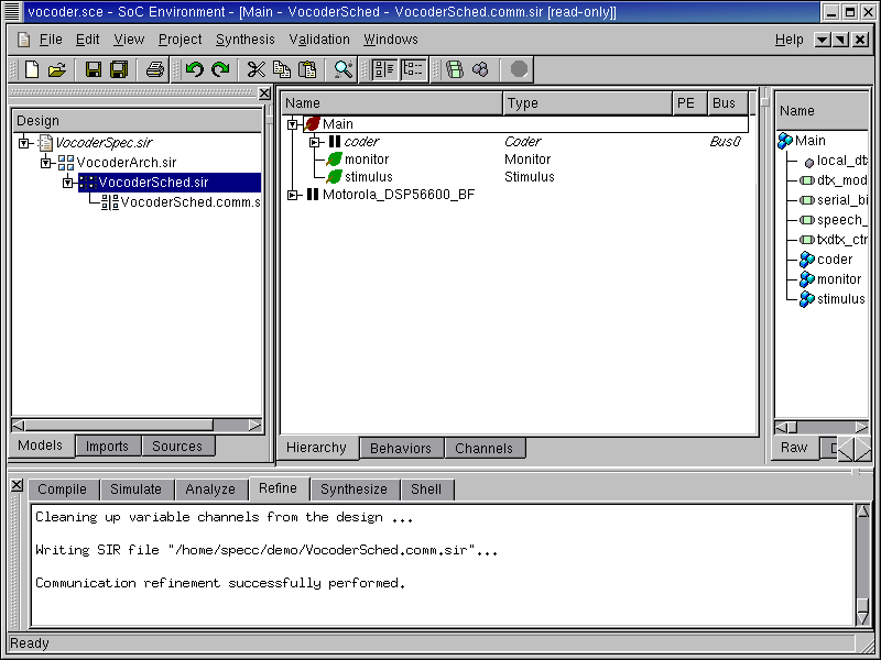
During communication refinement, note the various tasks being performed by the tool in the logging window. The tool reads in channel partitions, groups them together, imports selected busses and their protocols, implements variable channel communication on busses and finally inlines the bus drivers into respective components. Once communication refinement has finished, a new model is added in the project manager window. It is named "VocoderArch.comm.sir". Also note that we have a new design management window on the right side in the GUI.
3.4.3.3. Generate communication model (cont'd)
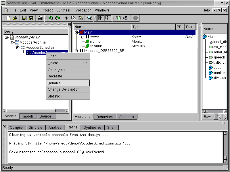
We now need to give our newly created communication model a reasonable name. To do this, right click on "VocoderArch.comm.sir" in the project manager window and select Rename from the pop-up menu. Now rename the model to "VocoderNet.sir".
3.4.3.4. Generate communication model (cont'd)
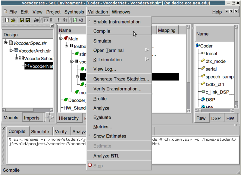
Simulate the resulting network model of the design by selecting Validation->Compile. Upon completion, select Validation->Simulate to validate its correctness.
3.4.3.5. Generate communication model (cont'd)
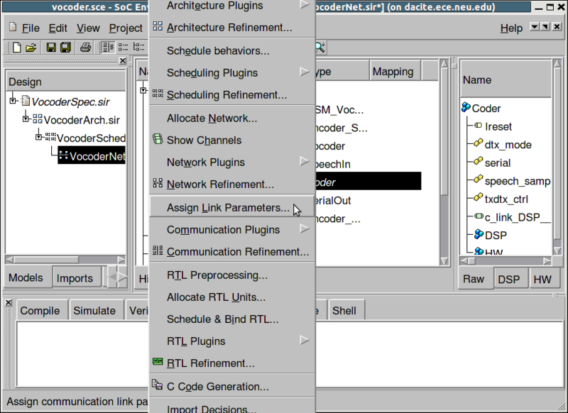
After network refinement, synthesis of communication in each bus segment of the system has to be done to complete the communication design process. For this, we start by setting parameters for all comunication links in the system. Select Synthesis->Assign Link Parameters.
3.4.3.6. Generate communication model (cont'd)
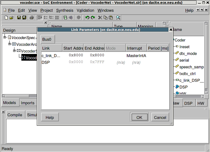
The Link Parameter dialog come up with one tab for each bus in the system. In the Link Parameters dialog, address maps and synchronization mechanisms for every channel and every PE interface on the busses have to be defined. On "Bus0," select the Start address of "c_link_DSP__HW" to be a value between 0x8000-0xFFFF and the Interrupt to be "MasterIntA" from the drop down menu. Finally, click OK to accept and confirm the bus parameter definition.
3.4.3.7. Generate communication model (cont'd)
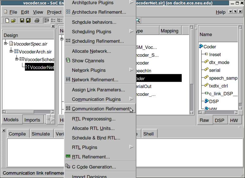
Select Synthesis->Communication Refinement to invoke the final communication refinement tool.
3.4.3.8. Generate communication model (cont'd)
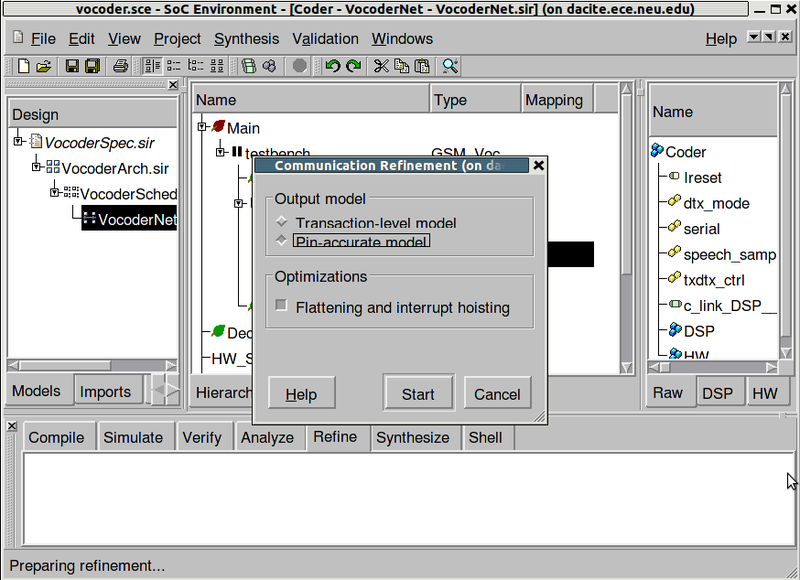
The dialog that pops up provides the option either to generate a Pin Accurate Model or a Transaction Level Model of the design. Accept the default option of generating a PAM and click Start to proceed.
3.4.4. Browse communication model
Like we did after architecture refinement, we browse through the communication model generated by the refinement tool. We have to first check whether it is semantically and structurally representing a model as described in our SoC methodology. To observe the model transformations produced by communication refinement, we need a graphical view of the model. This is done by left clicking to choose the "Coder" behavior in the design hierarchy window and selecting View->Chart from the menu bar.
3.4.4.1. Browse communication model (cont'd)
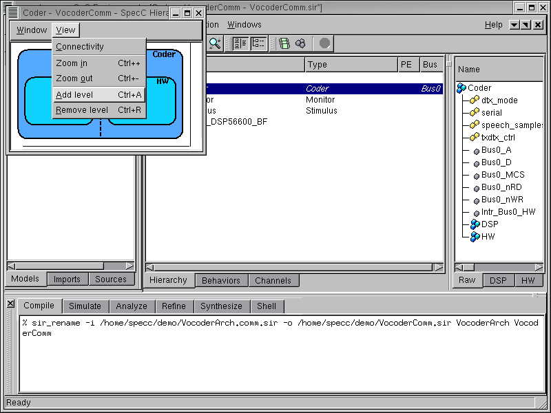
A new window pops up showing the model with DSP and HW components. We have to observe the bus controllers generated during refinement and the added details to the model. Hence, we select View->Add level from the menu bar to view the model with greater detail.
3.4.4.2. Browse communication model (cont'd)
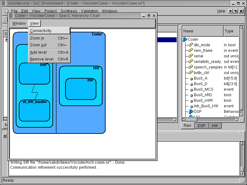
In the next level of detail, we can now see the interrupt handler "s0_HW_handler" behavior added in the master to serve interrupts from the HW slave. To view the actual wire connections of the system bus, enlarge window and select View->Connectivity from the menu bar.
3.4.4.3. Browse communication model (cont'd)
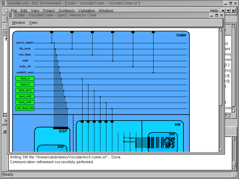
The wire level detail of the connection between components can now be seen in the window. Note that the system bus wires are distinguished by green boxes. Hence we see that the bus is introduced in the design and the individual components are connected with the bus instead of the abstract variable channels. On observing the hierarchical view further, we can see the drivers in each components. These drivers take the original variables and implement the high-level send/receive methods using the bus protocol.
We have thus seen that the structure of communication model follows the semantics of the model explained in our methodology. We may complete the browsing session by selecting Window->Close from the menu bar.
3.4.5. Simulate communication model (optional)
This section shows the simulation of the generated communication model. If the reader is not interested, she or he can skip this section and go directly to Section 3.5.
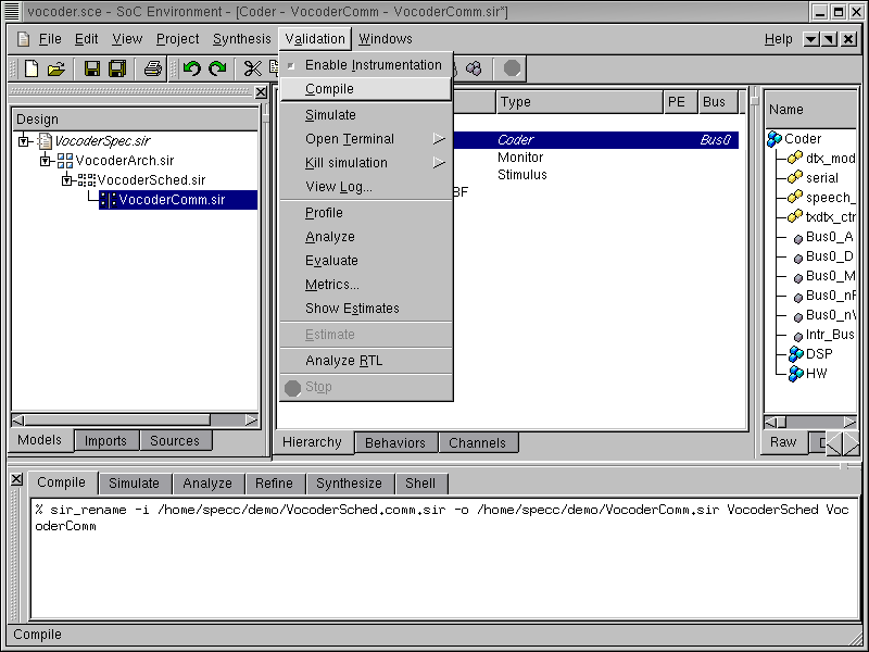
As a direct analogy to the validation of the architecture model, we have a step for validating the communication model. The newly generated model has already been verified to adhere to our notion of a typical communication model. We must now verify that the communication model generated after the refinement process is functionally correct or not. Toward this end, the model is first compiled. This is done by selecting Validation->Compile from the menu bar.
3.4.5.1. Simulate communication model (optional) (cont'd)
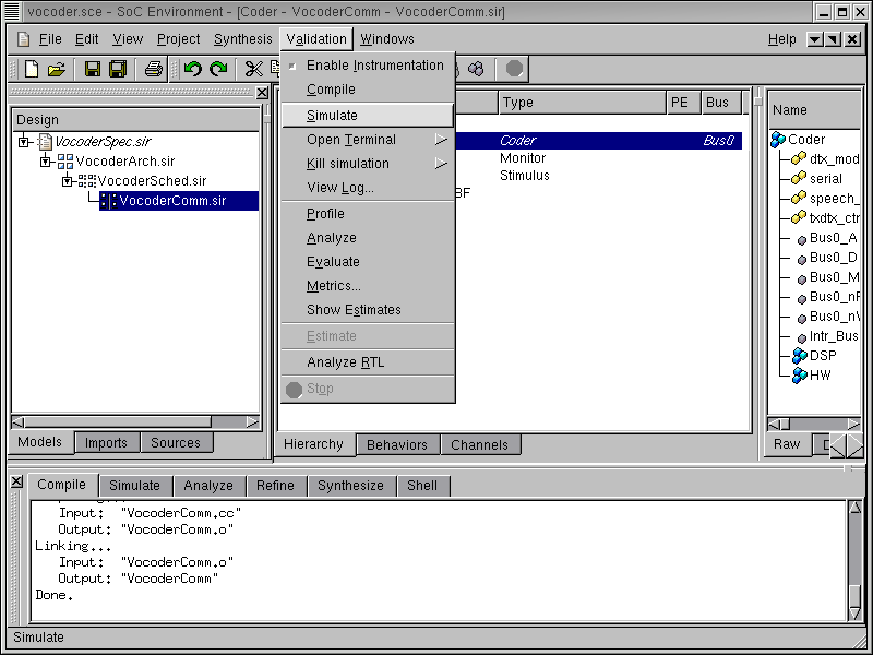
The model should compile without errors and this may be observed in the logging window. Once the model has successfully compiled, we must proceed to simulate it. This is done by selecting Validation->Simulate from the menu bar.
3.4.5.2. Simulate communication model (optional) (cont'd)
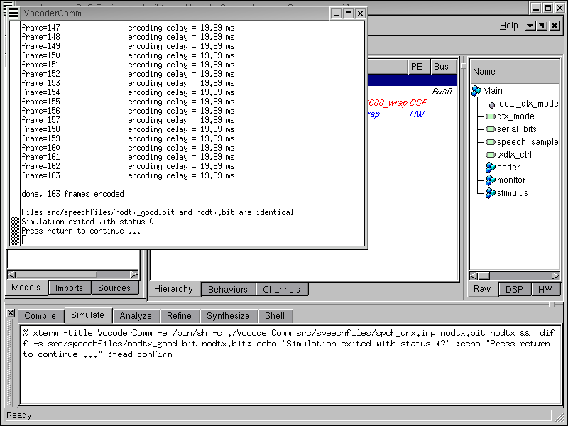
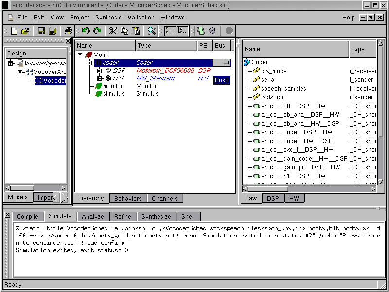
An xterm now pops up showing the simulation in progress. Note that simulation is considerably slower for the communication model than for the architecture and communication model. This is because of the greater detail and structure added during the refinement process. Also, it may be noted that the execution time for encoding each frame goes up to 19.89 ms from 19.77 ms, which we had for the model before communication synthesis. This is because communication synthesis replaced the abstract untimed transactions with detailed, timed bus protocols, which introduces non-zero communication delay. However, the execution time is still well within the 20 ms constraint for encoding each frame.
With the completion of correct model simulation, we are done with the phase of communication synthesis. Our new model now has two components connected by a system bus. The model is now ready for implementation synthesis.