2.2. Specification Capture
The system design process starts with the specification model written by the user to specify the desired system functionality. It forms the input to the series of exploration and refinement steps in the SoC design methodology. Moreover, the specification model defines the granularity for exploration through the size of the leaf behaviors. It exposes all available parallelism and uses hierarchy to group related functionality and manage complexity.
In this section, we go through the steps of creating a project in SCE and initiating the system design process. The various aspects of the specification are observed through simulation and profiling. Also, the model is graphically viewed with the help of SCE tools.
The models that we will deal with in this phase of system design are untimed functional models. The tasks of the system specification, referred to as behaviors in our parlance, follow a causal order of execution. The main idea in this section is to introduce the user to the SCE GUI and to demonstrate the capability of graphically viewing the behaviors and their organization in the specification model.
2.2.1. SCE window
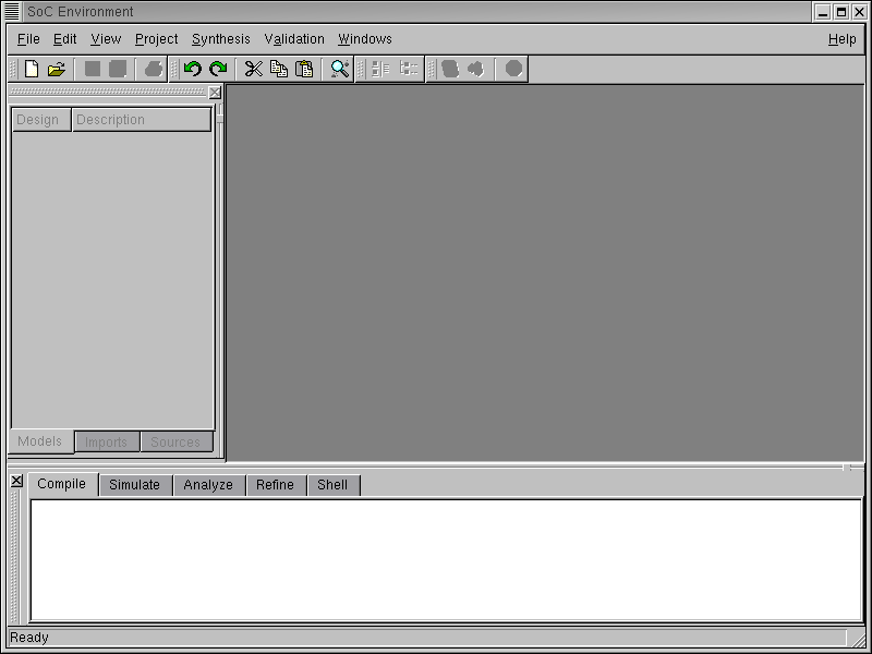
To launch the SCE GUI, simply run "sce" from the shell prompt. On launching the System-on-Chip Environment (SCE), we see the above GUI. The GUI is divided broadly into three parts. First is the "project management" window on the top left part of the GUI, which maintains the set of models in the open projects. This window becomes active once a project is opened and a design is added to it. Secondly, we have the "design management" window on the top right where the currently active design is maintained. It shows the hierarchy tree for the design and maintains various statistics associated with it. Finally, we have the "logging" window at the bottom of the GUI, which keeps the log of various tools that are run during the course of the demo. We keep logs of compilation, simulation, analysis and refinement of models.
The GUI also consists of a tool bar and shortcuts for menu items. The File menu handles file related services like opening designs, importing models etc. The Edit menu is for editing purposes. The View menu allows various methods of graphically viewing the design. The Project menu manages various projects. The Synthesis menu provides for launching the various refinement tools and making synthesis decisions. The Validation menu is primarily for compiling or simulating models.
2.2.2. Open project
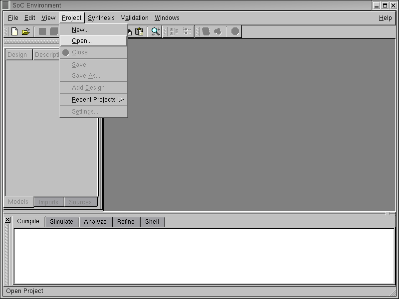
The first step in working with SCE is opening a project. A project is associated with every design process since each design might impose a different set of databases or dependencies. The project is hence used by the designer to customize the environment for a particular design process. We begin by selecting Project->Open from the menu bar.
2.2.2.1. Open project (cont'd)
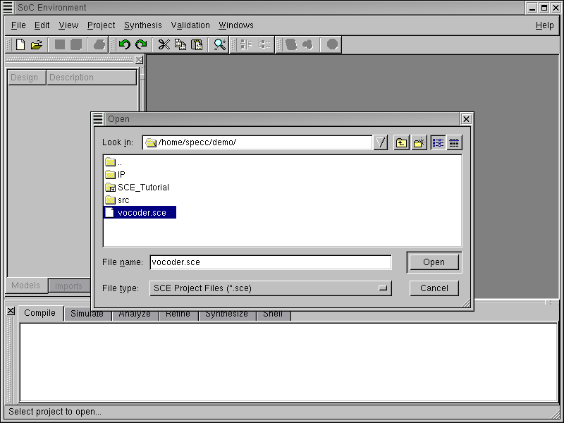
A Open file window pops up. For the purpose of the demo, a project is pre-created. We simply open it by selecting the project "vocoder.sce" and left click on Open button on the right corner of the the pop-up window.
2.2.2.2. Open project (cont'd)
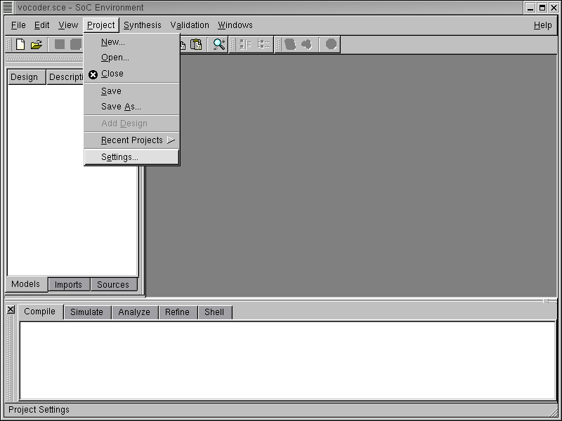
Since we need to ensure that the paths to dependencies are correctly set, we now check the settings for this precreated "vocoder.sce" project by selecting Project->Settings... from the top menu bar.
2.2.2.3. Open project (cont'd)
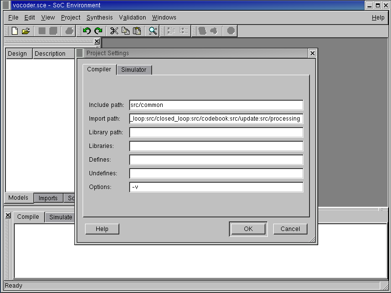
We now see the compiler settings showing the import path for the model's libraries and the '-v' (verbose) option. The Include path setting gives the path which is searched for header files. The Import path is searched for files imported into the model. The Library path is used for looking up the libraries used during compilation. There are also settings provided for specifying which libraries to link against, which macros to define and which to undefine. These settings basically form the compilation command. To check the simulator settings, left click on the Simulator tab.
2.2.2.4. Open project (cont'd)
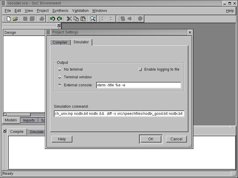
We now see the simulator settings showing the simulation command for the "vocoder.sce" project. There are settings available to direct the output of the model simulation. As can be seen, the simulation output may be directed to a terminal, logged to a file or dumped to an external console. For the demo, we direct the output of the simulation to an xterm. Also note that the simulation command may be specified in the settings. This command is invoked when the model is validated after compilation. The vocoder simulation processes 163 frames of speech and the output is matched against a golden file. Press OK to proceed.
2.2.3. Open specification model
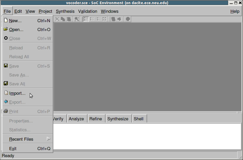
We start with the specification that was already captured as a model. We open this model to see if it meets the desired behavior. Once the model is validated to be "golden", we will start refining it and adding implementation details to it. We open the specification model for the Vocoder example by selecting File->Import from the menu bar.
2.2.3.1. Open specification model (cont'd)
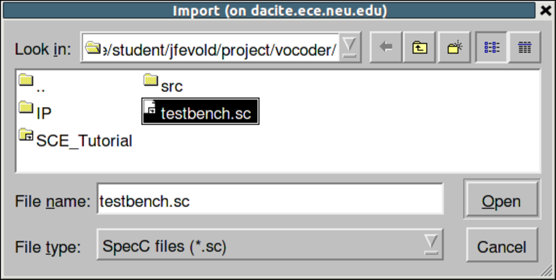
A file Open window pops up showing the SpecC internal representation (SIR) files. The internal representation files are a collection of data structures used by the tools in the environment. They uniquely identify a SpecC model. At this time however, the design is available only in its source form. We therefore need to start with the sources. Select "SpecC files (*.sc)" to view the source files.
2.2.3.2. Open specification model (cont'd)
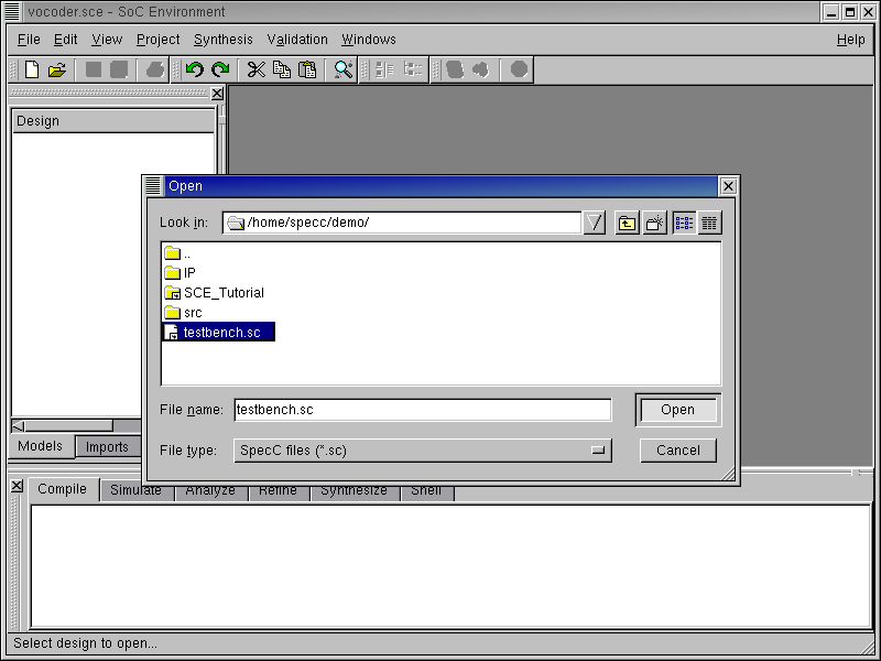
The Open is updated to show the available source files of the GSM Vocoder design specification. Select the file containing the top hierarchy of the model. In this case, the file is "testbench.sc". The testbench instantiates the design-under-test (DUT) and the corresponding modules for triggering the test vectors and for observing the outputs. To open this file Left click on Open.
2.2.3.3. Open specification model (cont'd)
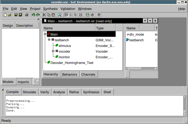
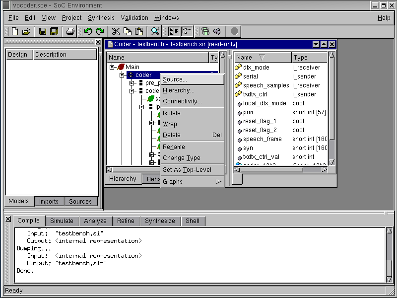
Note that a new window pops up in the design management area. It has two sub-windows. The sub-window on the left shows the Vocoder design hierarchy. The leaf behaviors are shown with a leaf icon next to them. For instance, we see two leaf behaviors: "stimulus", which is used to feed the test vectors to the design, and "monitor", which validates the response. "coder" is the top behavior of the Vocoder model. It can be seen from the icon besides the "coder" behavior that it is an FSM composition. This means the Vocoder specification is captured as a finite state machine. Also note in the logging window that the SoC design has been compiled into an intermediate format. Upon opening a source file into the design window, it is automatically compiled into its unique internal representation files (SIR) which in turn is used by the tools that work on the model.
2.2.3.4. Open specification model (cont'd)
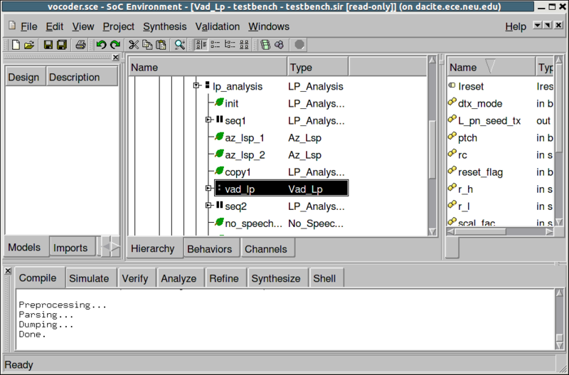
The model may be browsed using the design hierarchy window. Parallel composition is shown with || shaped icons and sequential composition with ':' shaped icons. On selecting a behavior in the design hierarchy window, we can see the behavior's characteristics in the right sub-window. For instance, the behavior "vad_lp" has ports shown with yellow icons, variables with gray icons and sub-behaviors with blue icons.
2.2.3.5. Open specification model (cont'd)
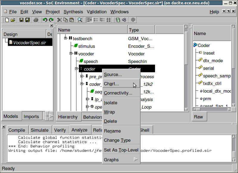
Before making any synthesis decisions, it is important to understand the composition of the specification model. It is useful because the composition really tells us which features of the model may be exploited to gain maximum productivity. Naturally, the most intuitive way to understand a model's structure is through a graphical representation. Since system models are typically very complex, it is more convenient to have a hierarchical view which may be easily traversed. SCE provides for such a mechanism. To graphically view the hierarchy, from the design hierarchy window, select "coder". Right click and select Hierarchy. Notice that the menu provides for a variety of services on individual behaviors. We shall be using one or more of these in due course.
2.2.4. Browse specification model
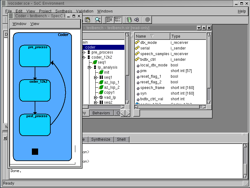
A new window pops up showing the Vocoder model in graphical form. As noted earlier, the specification is an FSM at the top level with three states of pre-processing, the bulk of the coder functionality itself and finally post-processing.
2.2.4.1. Browse specification model (cont'd)
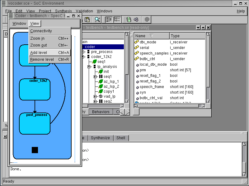
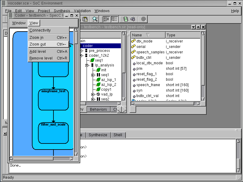
At this stage, we would like to delve into greater detail of the specification. To view the model graphically with higher detail, select View->Add level. Perform this action twice to get a more detailed view. As can be seen, the View menu provides features like displaying connectivity of behaviors, modifying detail level and zooming in and out to get a better view.
2.2.4.2. Browse specification model (cont'd)
Zoom out to get a better view by selecting View->Zoom out
2.2.4.3. Browse specification model (cont'd)
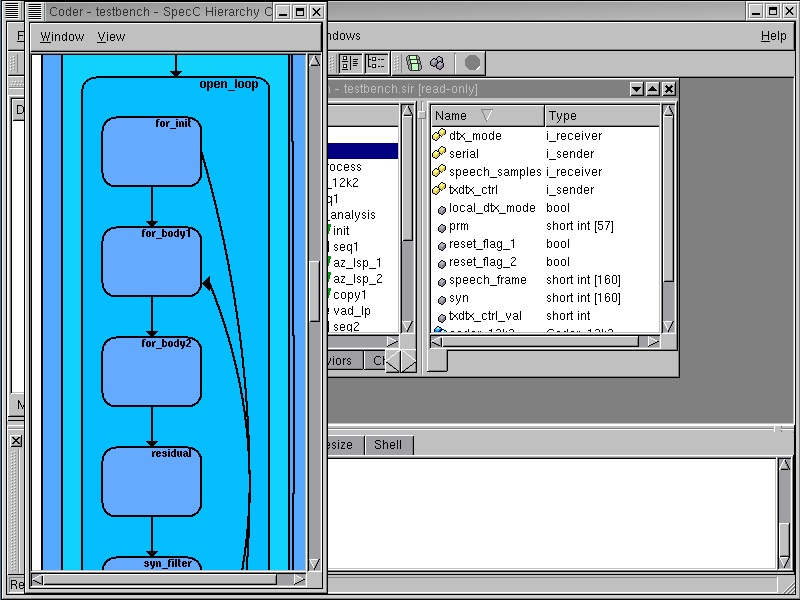
Scroll down the window to see the FSM and sequential composition of the Vocoder model. Note that the specification model of the GSM Vocoder does not contain much parallelism. Instead, many behaviors are sequentially executed. This is due to the several data dependencies in the code. For our implementation, this is an important observation. Since there is not much parallelism in the code to exploit, speedup can be achieved only by use of faster components. One way to speed up is to use dedicated hardware units.
Exit the hierarchy browser by selecting Window->Close
2.2.5. View specification model source code
We can also view the source of the models conveniently in SCE. For example, to check the source for behavior "coder", just click on the row in the hierarchy to select it. Then right click to bring up a menu and click on Source.
2.2.5.1. View specification model source code(cont'd)
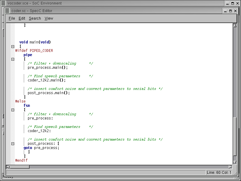
The SpecC Editor pops up containing the source code for the selected behavior. Changes to the source code can be made using the editor. After reviewing the source code, close the editor by selecting File->Close from its menu bar.